
All The Parts Forming The Slide Valve And Spindle Assembly Completed
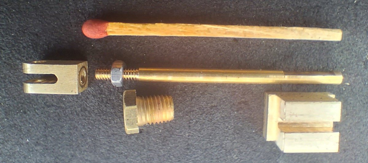
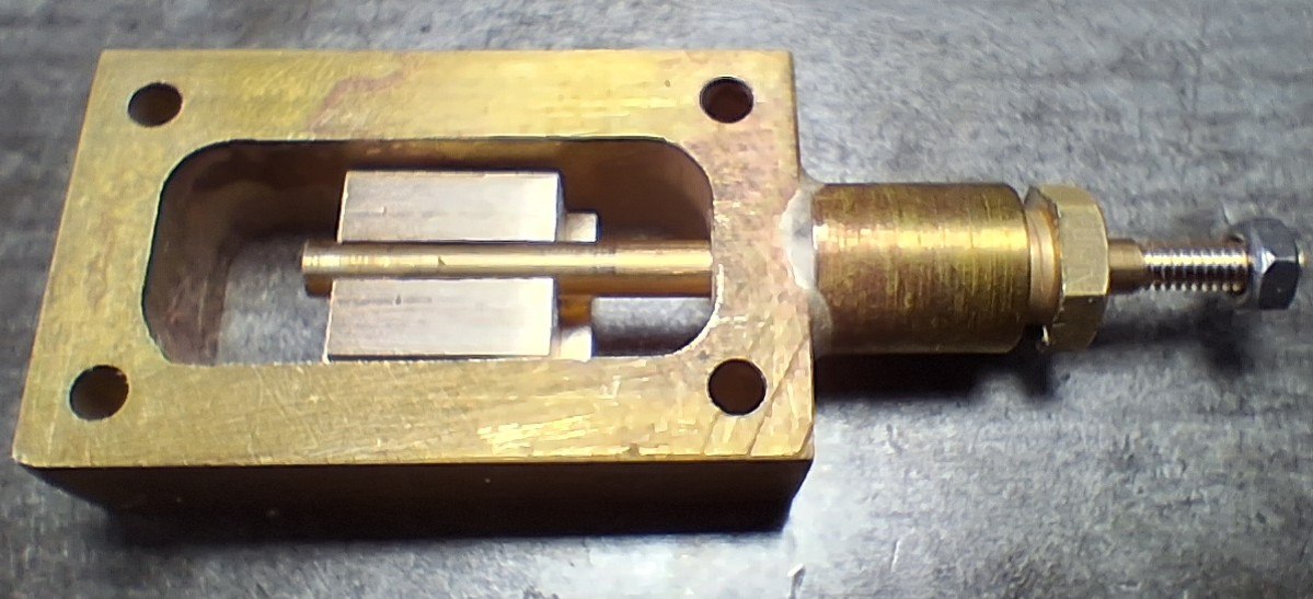
Photo of all the parts completed forming the Slide Valve and Spindle assembly:-
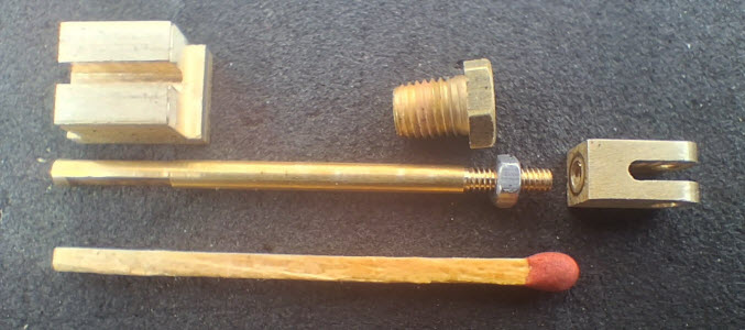
Slide Valve Spindle Clevis Components
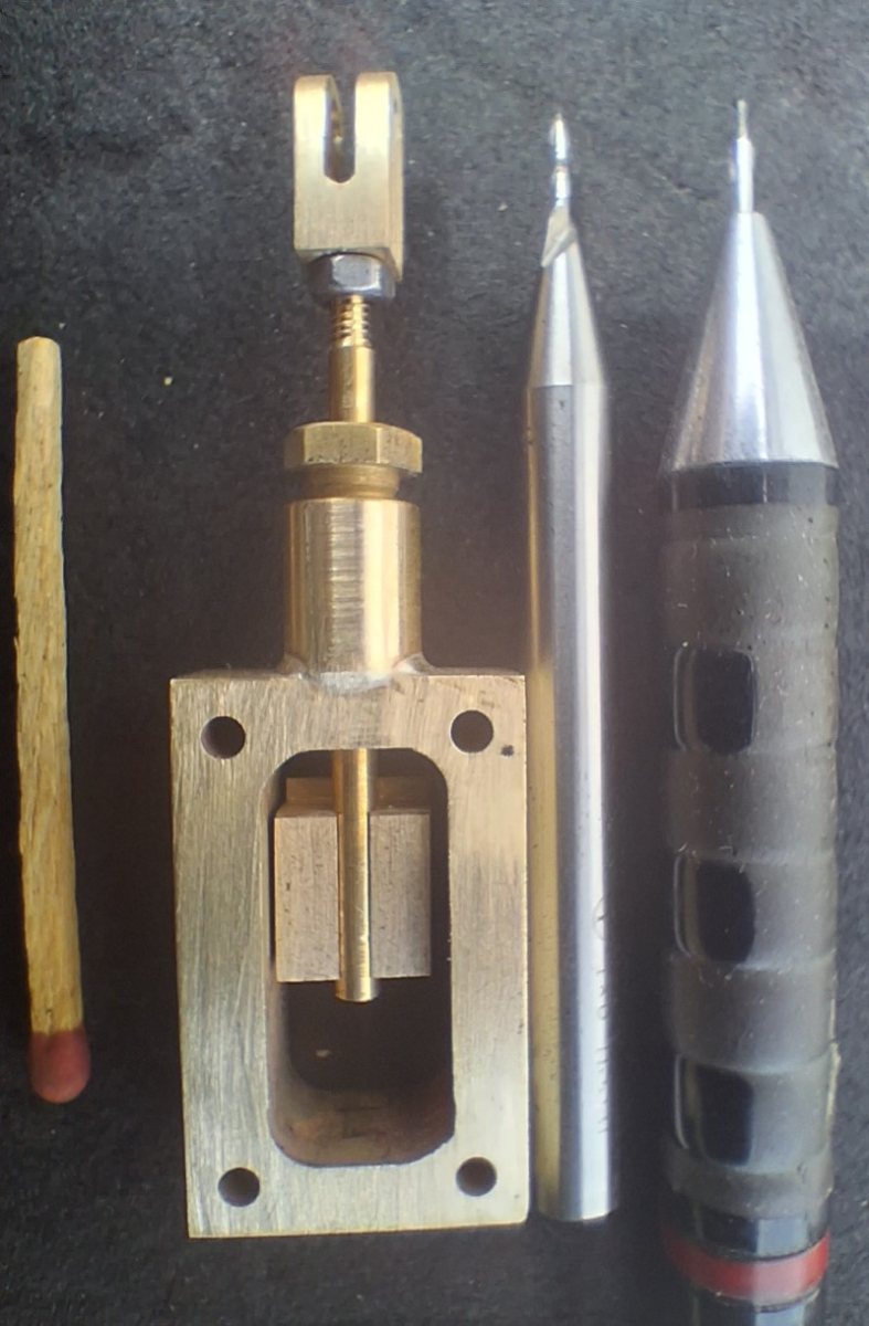
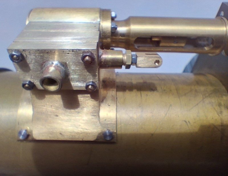
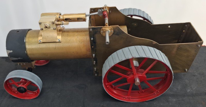
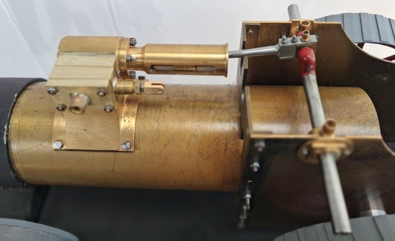
Photo of the Slide Valve Chest components installed in the Engine:-
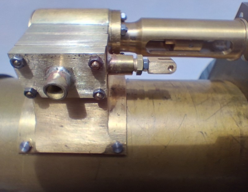
Slide Valve Chest Components on Engine
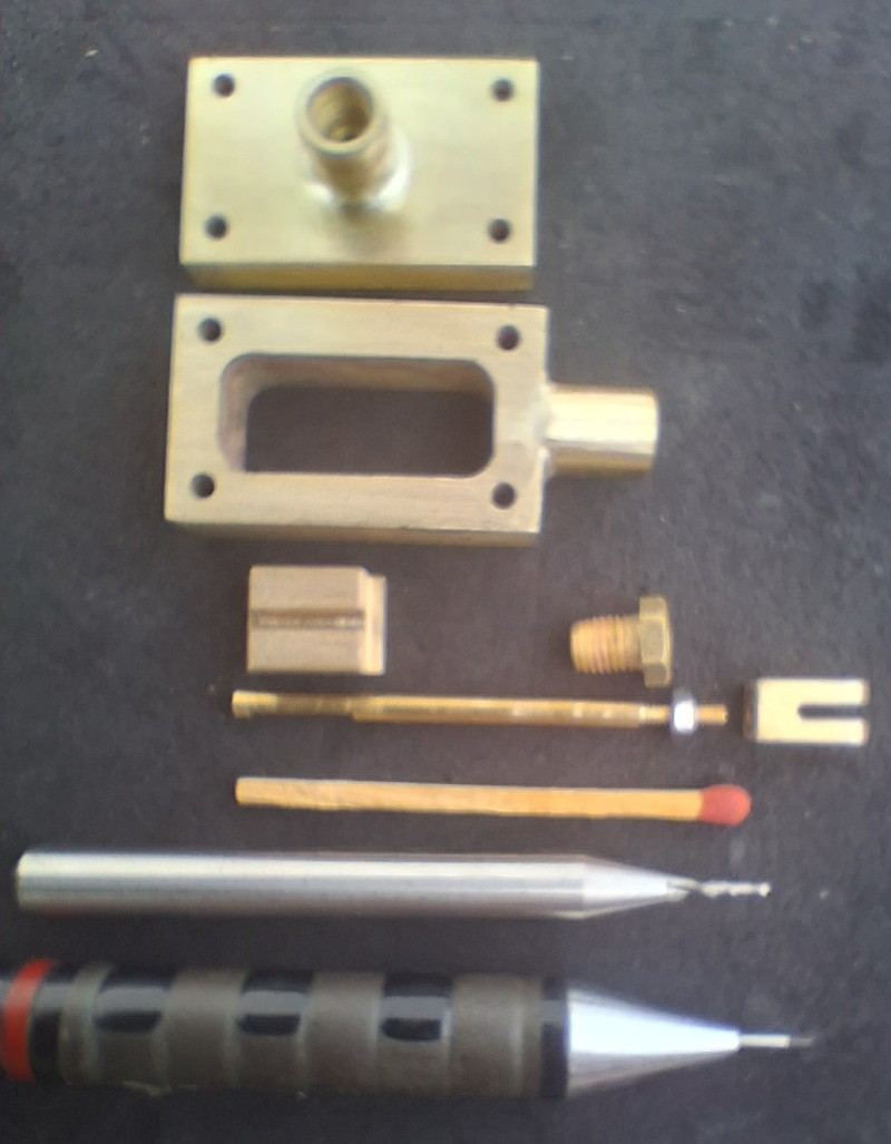
I have now completed the slide valve components for the 3/4″ scale Bassett Lowke Traction Engine Model. These components include;-
- The Slide Valve itself
- Spindle
- Spindle Gland Bush
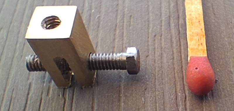
- Reversing Link Clevis.
The photos show above and below show these components together with the Valve Chest and Valve Chest Cover, plus photos of the components assembled and mounted on the cylinder fixed to the boiler.
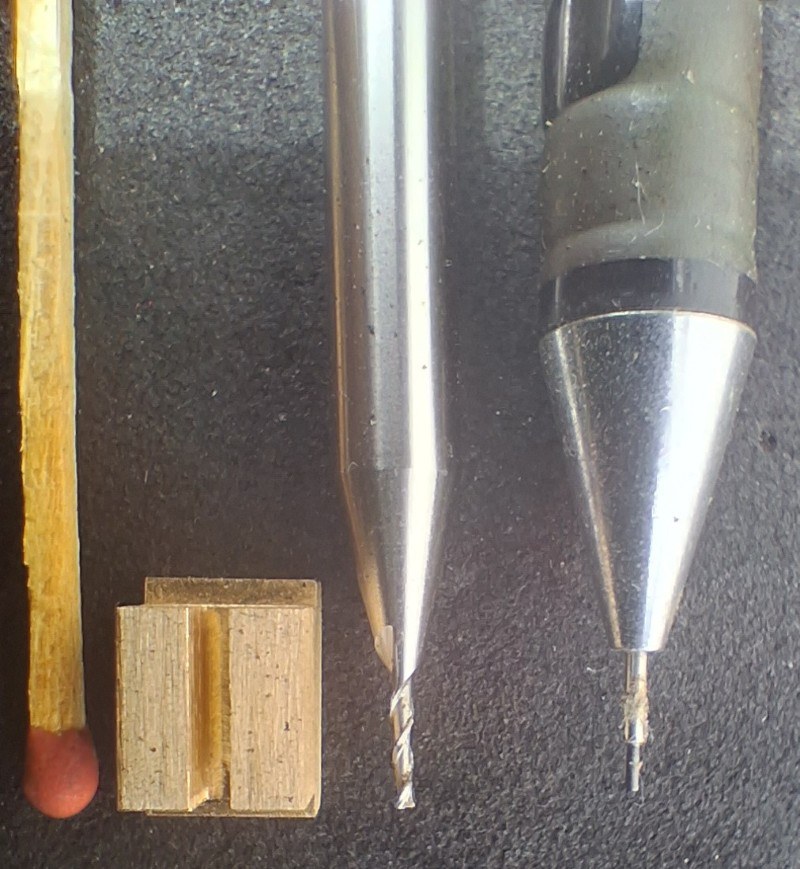
The parts are really tiny, but despite their small size and the comparatively large size of my lathes and milling machines they were not difficult to make extremely accurately following the principles outlined when making tiny components for my Gauge 1 Fowler LMS 2F Tank Locomotive.
In addition to the methods shown here to make tiny parts, click here to learn my other tricks to make tiny parts on big machine tools
More Photos Of Tiny Component Parts
Click on the image then click the <> arrows to navigate. Escape to exit.
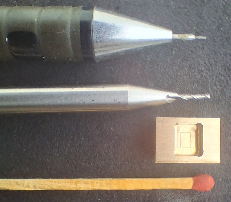
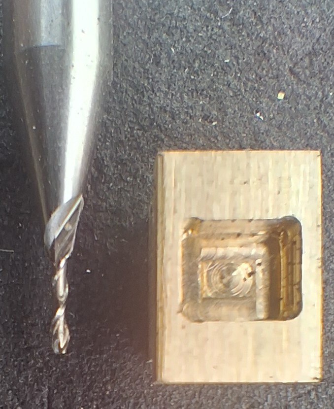


More Photos Of The Slide Valve Components on the Engine
Click on the image then click the <> arrows to navigate. Escape to exit.
Machining The Components
Here are sets of photos showing the machining processes, part-by-part.
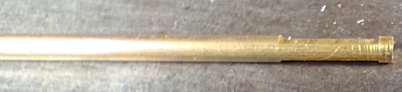
Valve Spindle Machining
Points to note when viewing the photos.
1. Milling the Flats
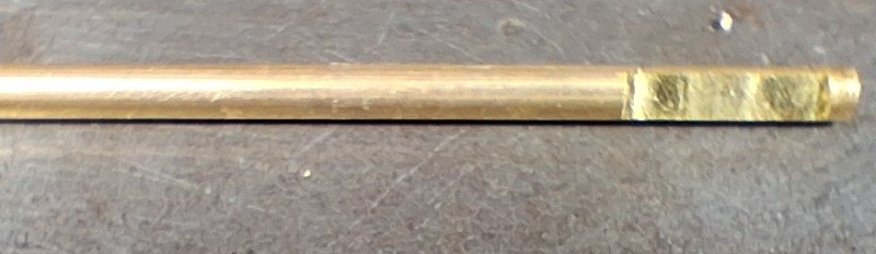
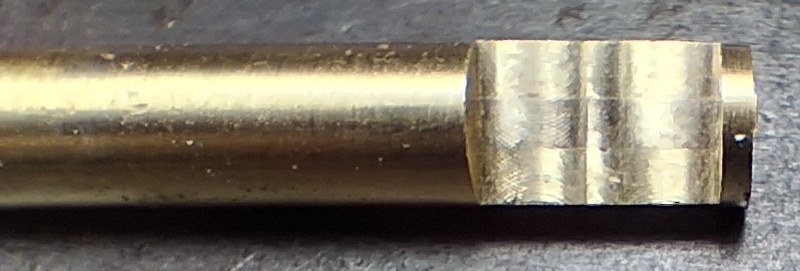
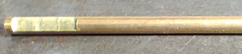
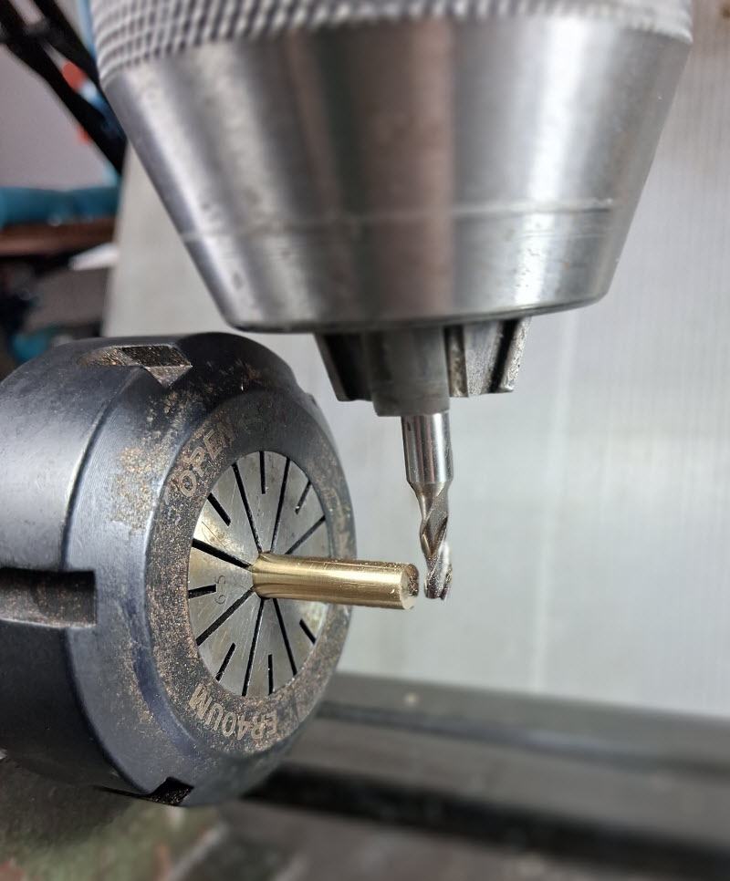
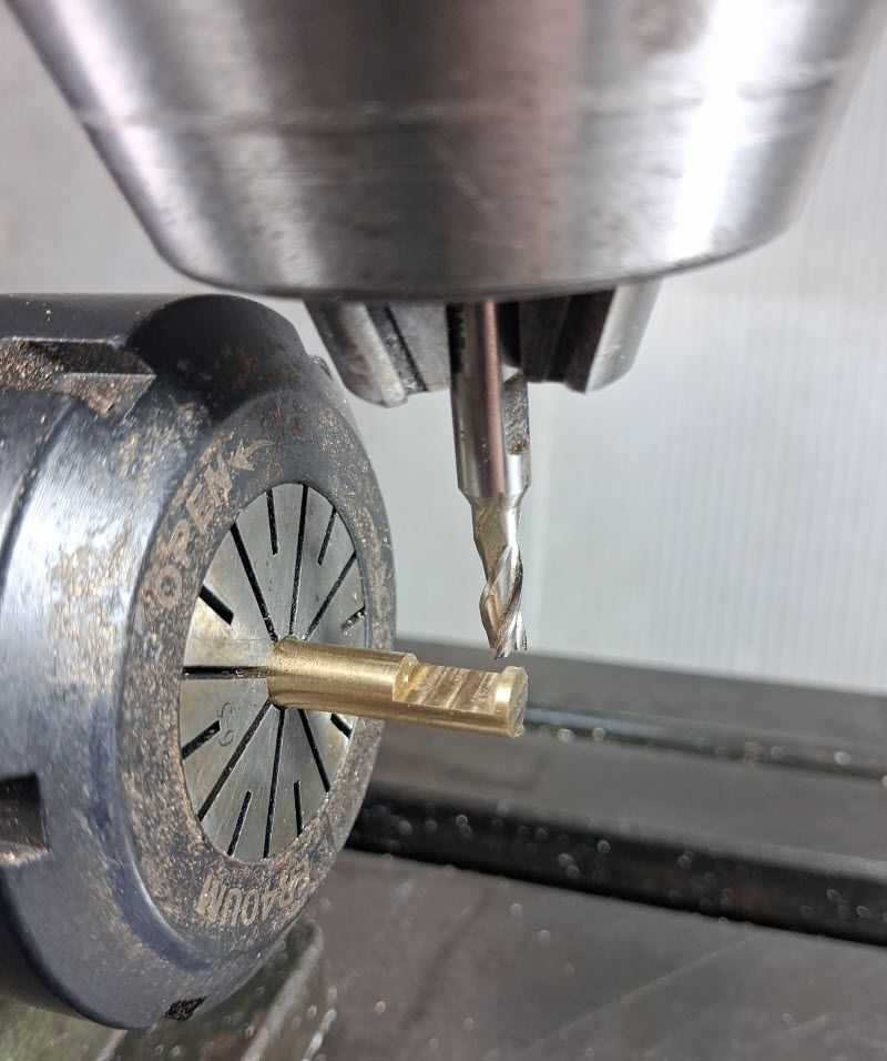
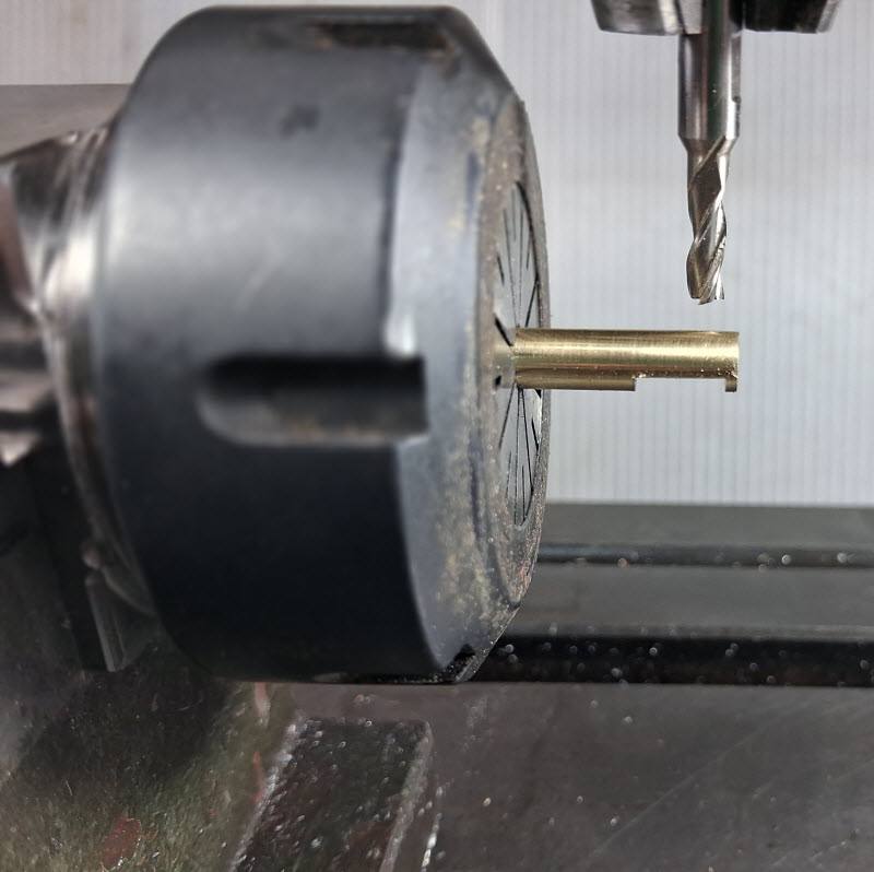
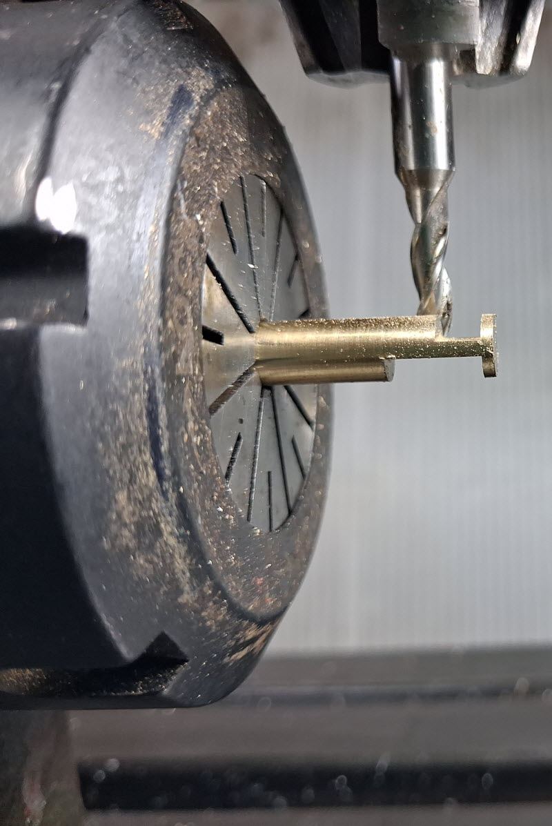
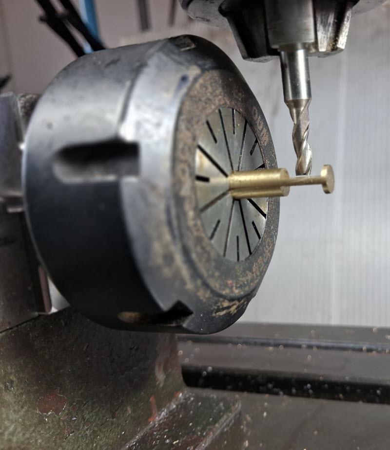
Two flats were milled in the spindle to fit in the slot machined in the slide valve itself. The slot is 1.5mm wide and was created by chain-drilling and milling with a 1.5 mm end mill. (You will see this operation in the Slide Valve Machining gallery.)
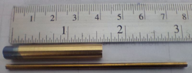
In order to provide support to the thin (3/32″, <2.5mm diameter) valve spindle when milling, the spindle was Loctited into a 3/32″ hole drilled axially in a piece of 6mm diameter brass rod turned down from 1/4″ dia stock, to suit my ER42 collets. This gave ample support for the milling process.
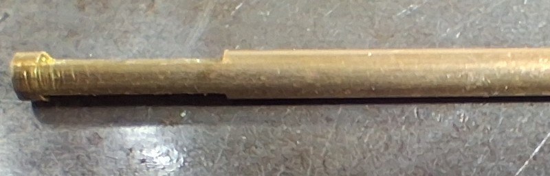
The last photo shows the 6mm support rod at the end of the milling process after the valve spindle had been removed.
2. Collet Holder and Vice Jaw Stop
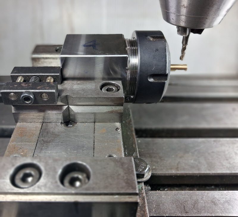
Note the use of the square collet block to mill the opposite flat and the vice jaw stop to locate it axially when flipping over.
3. Flat Thickness
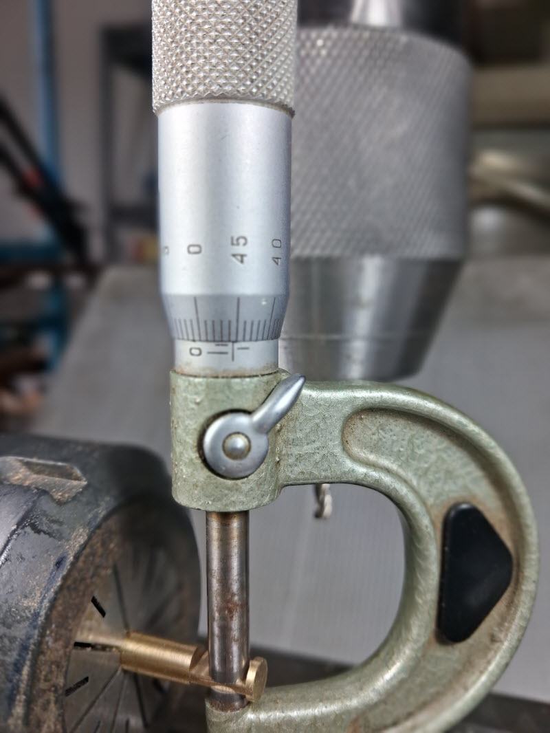
It’s always difficult (on this milling machine anyway – a Bridgeport clone) to machine down to an exact position. In this case, as you can see my the micrometer, I managed to achieve 1.45mm thickness, giving a ‘two thou’ clearance in the slide valve slot. Don’t want it too tight otherwise the slide valve might not seat correctly on the valve face.
4. End Mill holder
Yes, I used a drill chuck (robust keyless type) to hold the end mill, because a standard ER 32 Collet would have fouled the vice jaws. Rigidity of the end mill cutter was never an issue.
Click on the image then click the <> arrows to navigate. Escape to exit.



Slide Valve Machining
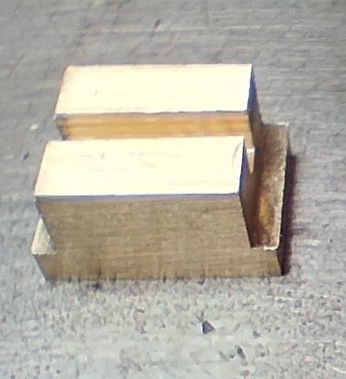
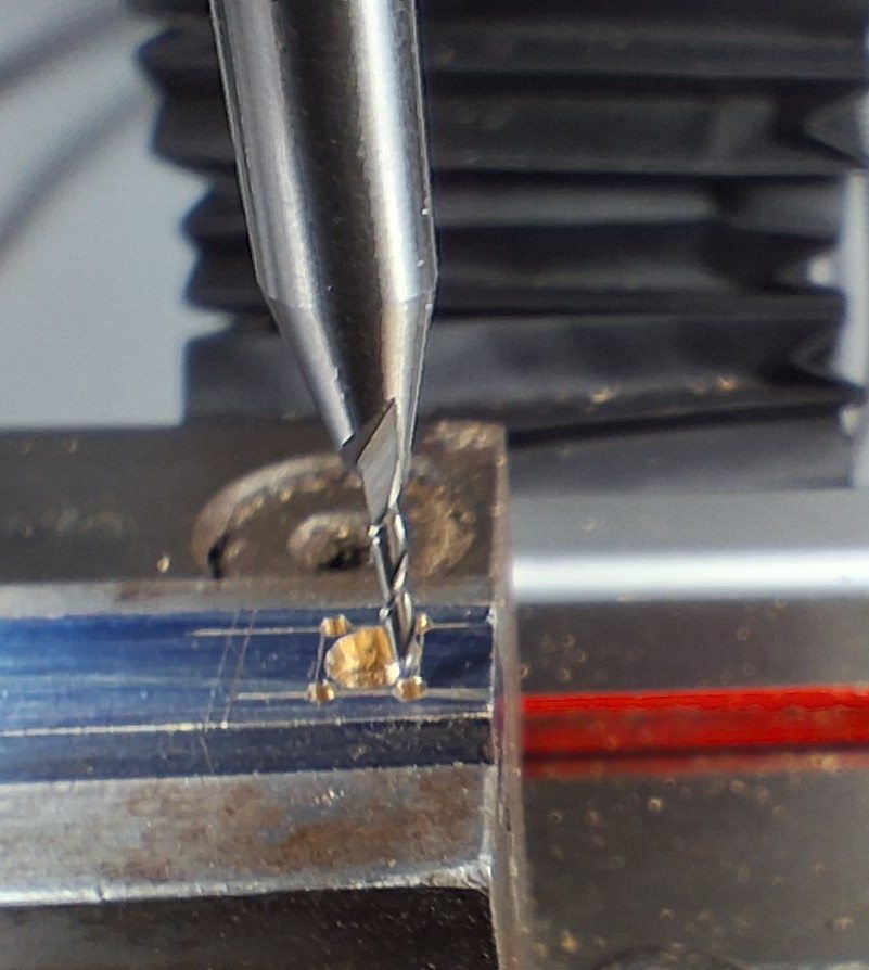
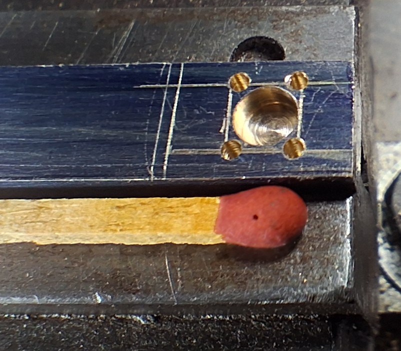
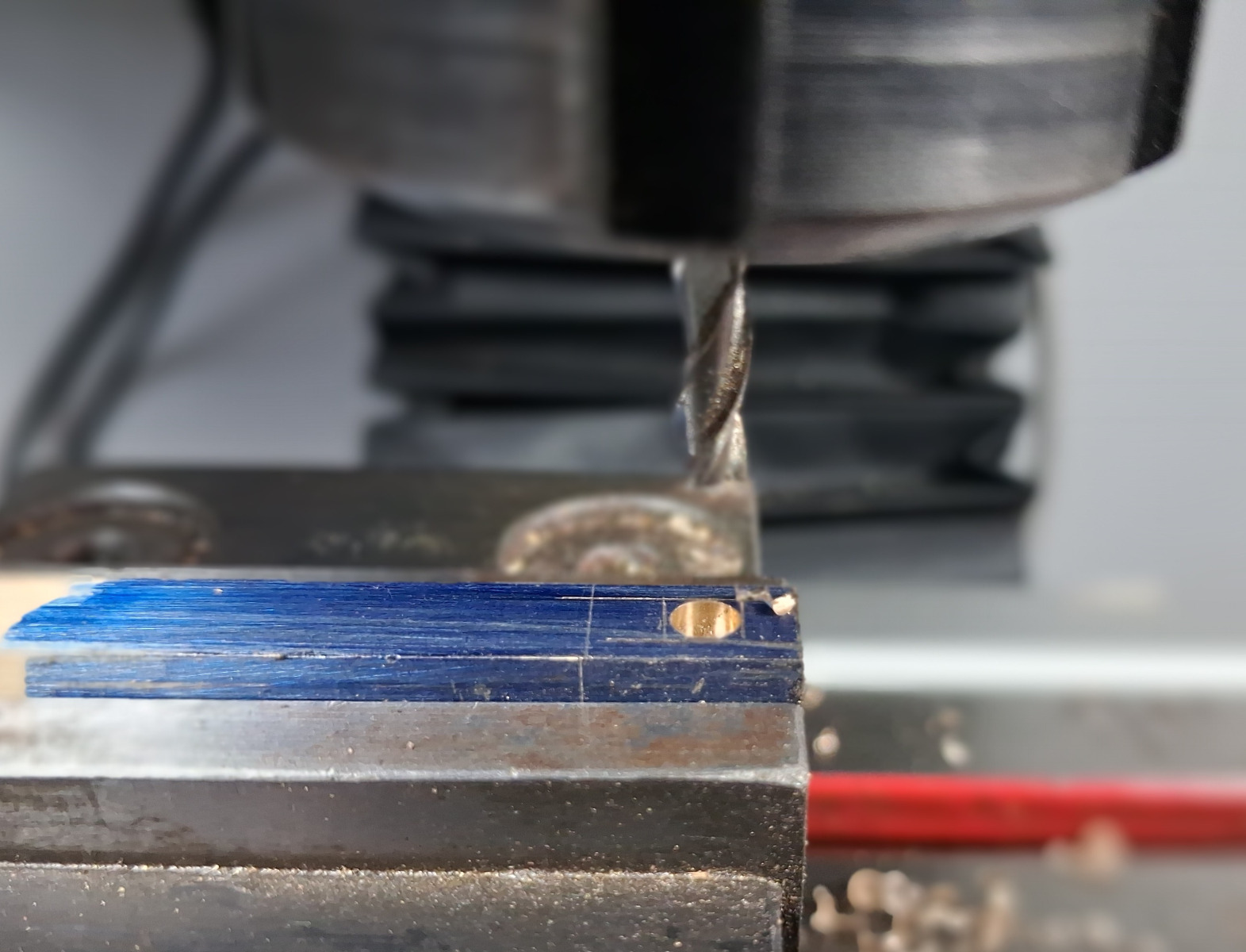
The main trick here to make this tiny part is to use a long piece of stock material so that there is plenty of material to grip in the milling machine vice jaws. The main steps I followed are:-
After marking out, mill the main slide valve cavity (which is 3/16″ square by 3/32″ deep) to the correct depth with an undersized (4mm) end mill.
Using the DRO mill the four corners using a 1mm end mill.
Using the DRO mill the four sides to dimension using a 1.5mm end mill.
Flip the work to mill the slot. Chain-drill the slot with an undersized drill and clean up with a 1.5mm end mill.
Note that these tiny sized end mills are very weak and easy to break. I took light cuts of 0.2 mm (8 ‘thou’) so 12 passes required – not so bad since the distance is so short.
This is what AI says about the subject of using tiny end mills:-
| For a 1 mm diameter end mill in brass, the safe axial depth of cut (ADOC) is typically 0.1 mm to 0.3 mm per pass. Because small-diameter end mills are fragile, avoiding bit breakage requires balancing this shallow depth with conservative feed and speed settings:
Micro-machining tiny details like a 1 mm bit requires a machine that can handle high spindle speeds without deflection. |
Milling Machine
By the way, I didn’t machine these slide valve parts on the big ARGO Mill (Bridgeport clone), instead I used the smaller and more sensitive PX-20LV Mill that I had only recently added a DRO to in order specifically to make these tiny Bassett Lowke Traction Engine Model parts. You can see the SINO DRO installation on PX-20LV Milling Machine here.
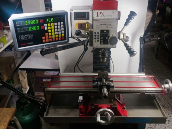
SINO DRO on PX-20LV Milling Machine
Click on the image then click the <> arrows to navigate. Escape to exit.



Reversing Link Clevis Machining
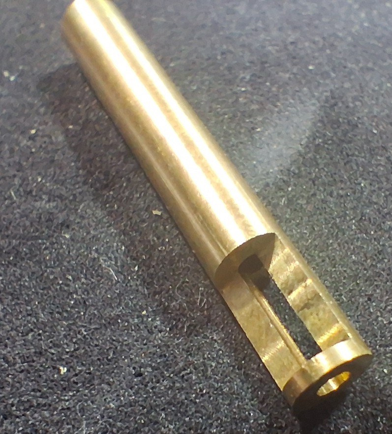
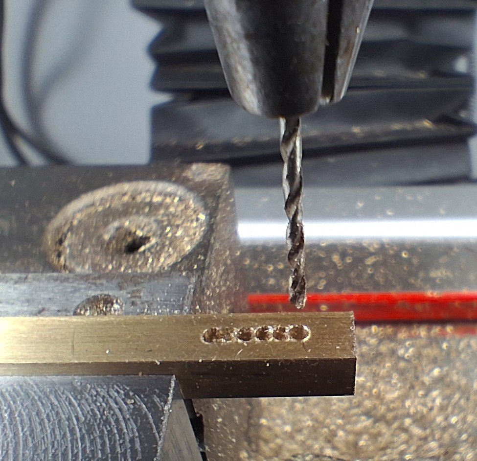
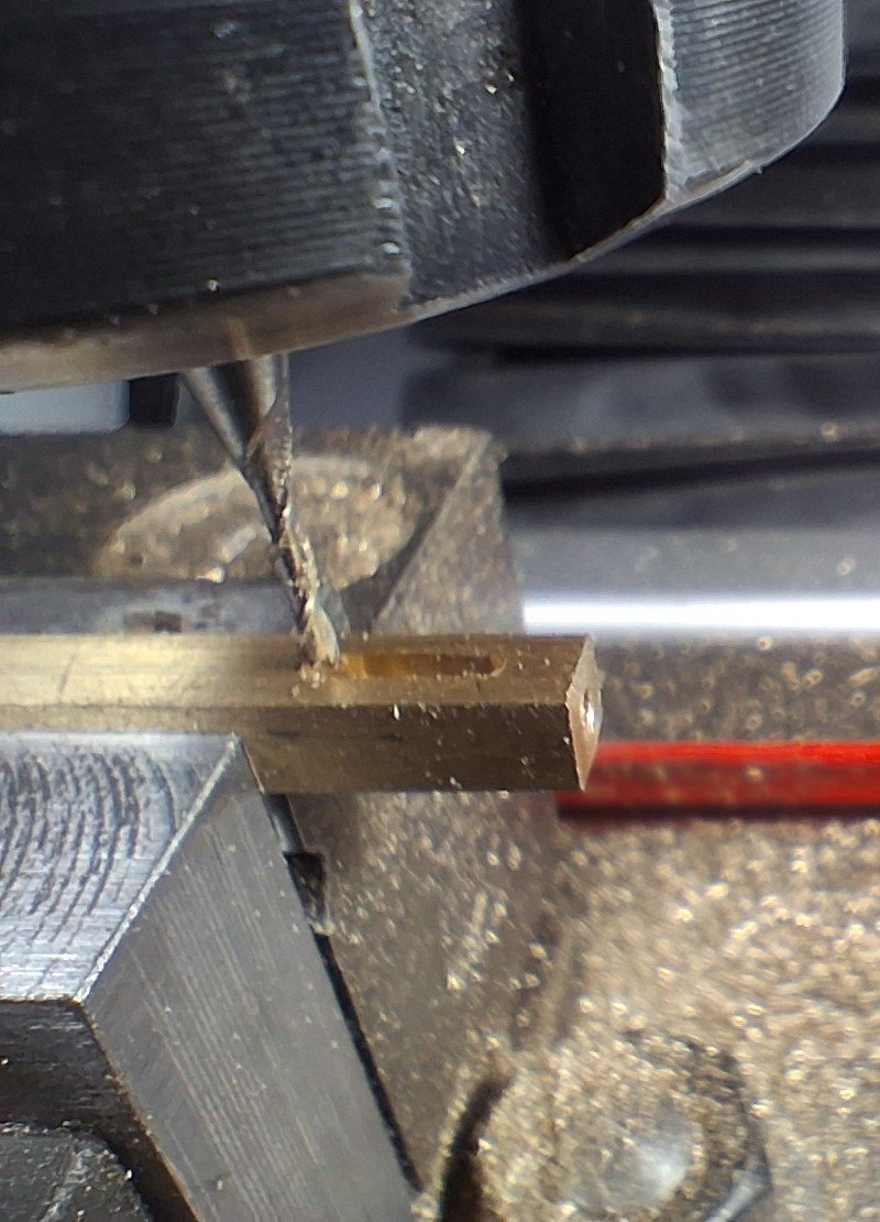
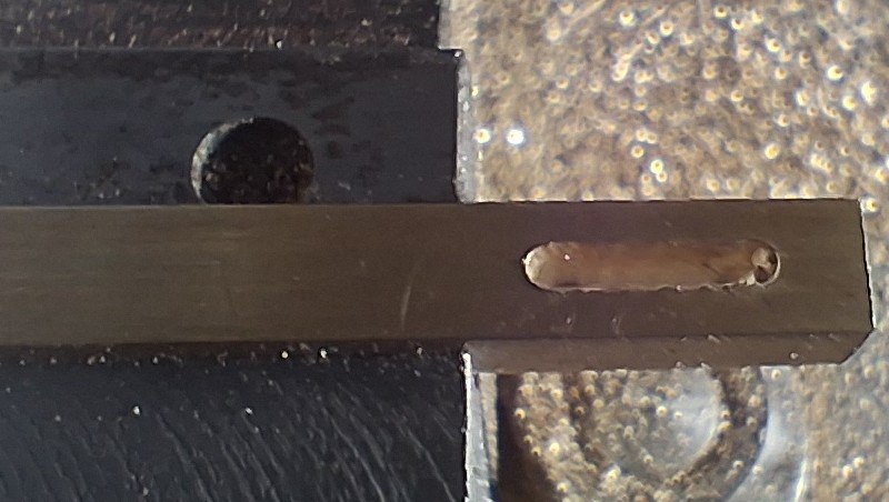
The trick here is to use a long piece of stock as explained for the Slide Valve to give plenty of material to hold in the milling vice, but also to NOT make the slot at the end of the stock.
If you try to make the slot at the end of the stock the thin side wall or ‘forks’ of the slot will deform and at best you’ll get a tapered slot. Instead make the slot a bit inboard of the end of the stock so that there remains a solid piece of material to separate and support the slot sides as it is machined.

CAD Drawing of Reversing Link Clevis
The next trick is to drill and tap the cross holes while the excess material is still available to give support to the drill before cutting off and machining to final length.
Click on the image then click the <> arrows to navigate. Escape to exit.

Please Add Your Comments Below
As the Youtubers say “It helps the algorithm and helps to get the message out to more people”.
Here, of course the algorithm refers to the online search engine algorithms (e.g. Google). I hope that we all want more people – especially model engineering types in Thailand – to join our group and enjoy the wonderful experience of Model Engineering In Thailand.
And/or, if you would like to add your comments in the Forum you can do so here.