Making A Model Steam Engine In Thailand From A Stuart Turner Casting Kit – Progress To Date
Photographs and a video showing the progress on building the Stuart Turner model Victoria steam engine from a kit of castings in my model engineering workshop in Thailand.
First a video because it shows that I have reached the stage where something is moving even if I have to spin it by hand!
Now let’s look at some progress photos taken today. Most of the parts are covered in grey primer applied by aerosol spray (unless they are machined surfaces).
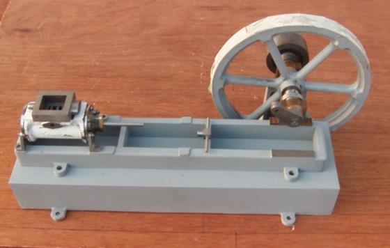
First a general photo of the steam engine assembled with the pieces made to date:-
The rough look of the flywheel is masking tape on the machined portions to prevent the spray paint from landing.
The Secondary Base for the Victoria Steam Engine
You can see the engine base casting is sitting on another larger secondary base. In the book describing building the Stuart Turner Victoria Steam Engine “Building The Victoria – A 19th Century Steam Engine” by Andrew Smith he gives details of a wooden secondary base. There is no information on this secondary base in the Stuart Turner instructions nor on their drawings.
As it happened I had a piece of steel channel which was just about the right size for a secondary base so I added some feet and steel plates to fill the ends and I have what you can see in the photos. Although a wooden base is more authentic (and I may make one eventually) I am a bit concerned about alignment of the crankshaft with a wooden base. Wood shrinks and after some time the outboard crankshaft bearing would need some adjustment.
Anyway, I want a base made quickly to mount the engine on so it will stay as it is until the engine is finished.
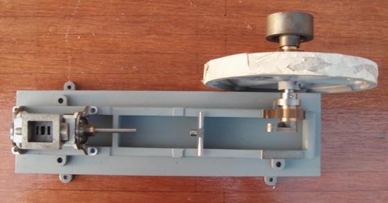
Next is a general view of the engine from the top.
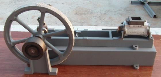
And next a view from the other side.
The Drive Belt Pulley
I haven’t machined any grooves in the belt pulley as shown on the Stuart Turner drawings yet. There are two reasons why not:-
- I don’t think that groves are appropriate. I think (and I’m prepared to be corrected on this) that flat belts would have been used which would demand a slightly ‘domed’ flat pulley. The book mentioned above does not show this pulley at all.
- I haven’t decided what the engine will be connected to (if anything) when it’s finished so i don’t know what kind of drive will be required.
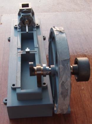
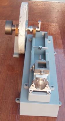
Now a photo looking from the flywheel end:-
And next a photo from the other end, which I call the rear:-
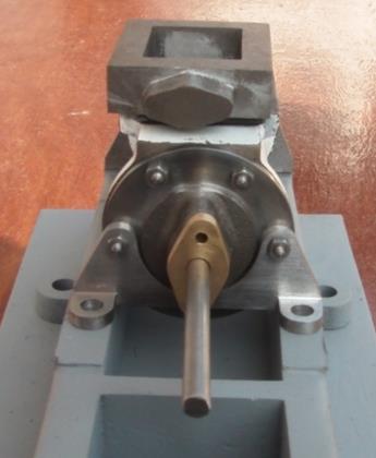
Next is a photo of the rear of the engine. It’s a close-up photo of the cylinder cover and the cylinder support bracket:-
A number of points to note here:-
- This is the second cylinder cover I have made. I turned the first one undersize after it jumped out of the three-jaw chuck. The casting did not have a very generous allowance to turn a chucking piece.
- The second cylinder cover (the one in the photo) was made from a piece of cast-iron bar I bought locally in Pakchong (Pak Chong). The cast iron turned OK but the iron is large-grained and it is impossible to get a fine finish on it.
- There are two more cylinder cover fixings that you can’t see in the photo. These are countersunk screws hidden under the bottom part of the cylinder mounting bracket. Took me a while to figure this out.
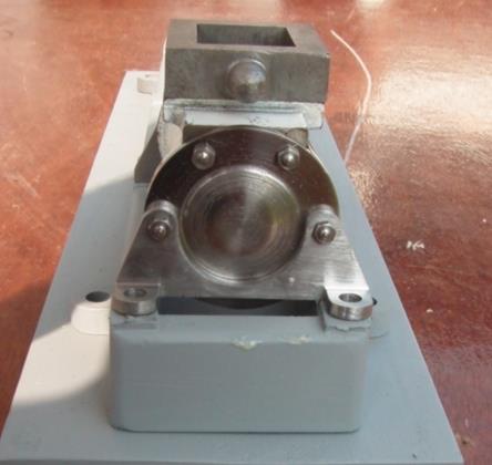
Now look at the close-up photo of front cylinder cover and cylinder support bracket:-
Again a few points to mention:-
- As with the rear cylinder cover there are two countersunk fasteners hidden under the cylinder mounting bracket.
- I had a difficult time when I made the Stuart Turner S50 horizontal mill engine (a much smaller model) lining the cylinder up with the crosshead guide bars To avoid that problem with the Victoria model I painstakingly made a jig to drill the holes in the cylinder covers and the cylinder support brackets to guarantee that the cylinder would be perfectly horizontal when the cylinder support brackets sit on a flat surface. Guess what. It rocks!
- The last point to mention is even more of an embarrassment. It won’t affect the functionality of the engine in the slightest but if I decide to sell the engine (probably) I will have to make a new part. Can you spot the mistake? It’s particularly annoying because having made the jig I mentioned drilling the cylinder cover holes was supposed to be foolproof!
Other Pages Showing Machining And Constructional Videos And Photos
That’s all for this page. I just wanted to record where we are with this model. There will be plenty of other pages showing the construction going forward and how I go to this point.
Please remember that this model is being made entirely in my model engineering workshop in Thailand. (Exception – the cylinder covers drilling jig was made in my other workshop in the UK)
