Making The Connecting Rod for the Bassett Lowke 3/4″ Scale Model Traction Engine
The Finished Connecting Rod And Comparisons
This connecting rod by virtue of it’s small (3/4″: foot) scale is very small, about 2 1/2″ (65mm) long, yet has most if not all of the details and components of the full-sized prototype engine.
First a few photo’s of the finished connecting rod:-
The first thing to mention is that the connecting rod itself is machined from solid stainless steel bar.
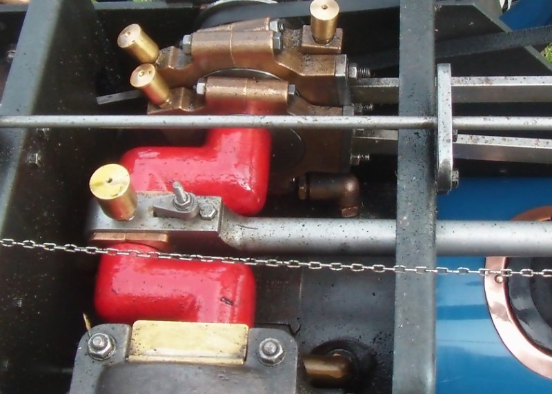
The first photo, below, shows the finished connecting rod – the tiny size and fine detail are obvious:-
BLTE Conn Rod Finished With Oiler
The next photo shows the same item but with the big-end oiler cap removed:-
BLTE Conn Rod Finished With Oiler Cap
Did you notice the 10BA fully shaped heads to the strap bolts with lock-nuts on top?
The next photo shows the connecting rod from my half-sized Little Samson traction engine. It’s about 3ft (1m) long and the BLTE connecting rod is about as long as the big-end bearing brasses in the photo below.
LSTE 6″ Scale Conn Rod
And here is the same Little Samson Connecting Rod with the Bassett Lowke Connecting Rod sitting on the Big-end Bearing:-
3/4″ Bassett Lowke Conn Rod on 6″ LSTE Big-End Bearing
Finished Component Parts
Here is a photo of all the finished component parts of the Conn Rod:-
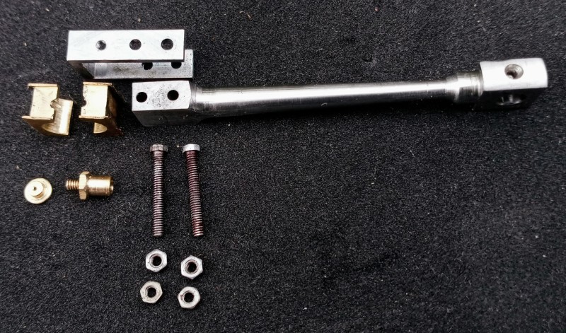
BLTE Conn Rod Finished Component Parts
Yes, I know that the 10BA screws (yes, they should be bolts) are a bit rusty and I might make new ones. Problem is sourcing the hexagon stock to make the heads for the screws and the nuts. As far as I know this is unavailable. If I make my own from scratch, and I have a method planned to enable that to be done, then I’ll make them from stainless steel.
Drawings
The Connecting Rod drawing by Bassett Lowke:-
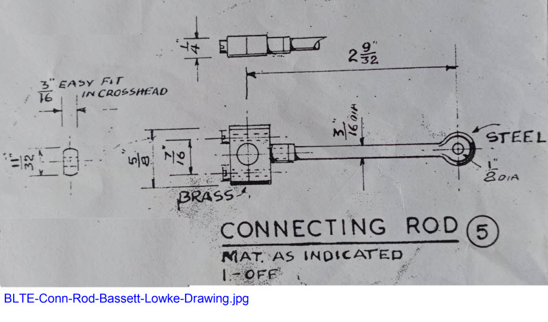
Bassett Lowke Conn Rod Drawing
You can clearly see what a very simple slab-sided design this is. Here is a photo of an actual Conn Rod made to the Bassett Lowke drawings:-
Bassett Lowke BLTE Conn Rod Crank per BL Drawings
The full-sized Allchin Connecting Rod looks nothing like that, of course, and here is an extract from the Allchin Book by W J Hughes:-
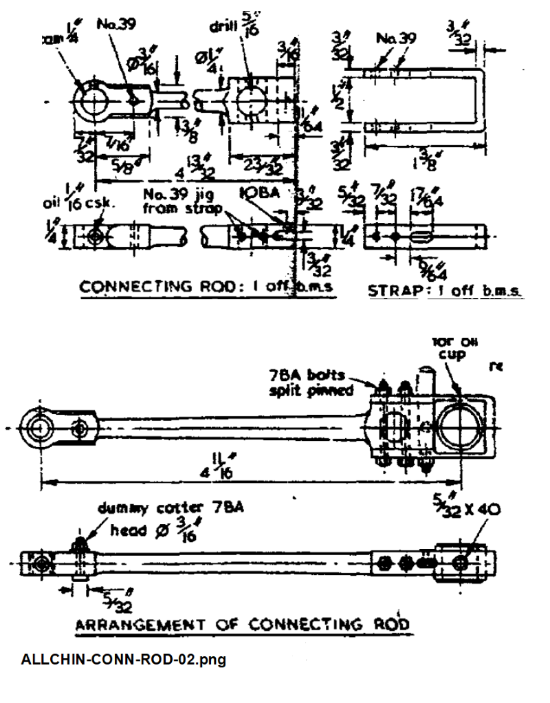
Allchin Conn Rod from a Drawing by W J Hughes
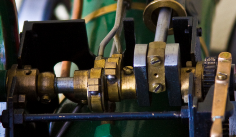
Also, I can show a 3″ Scale Allchin Conn Rod, at least showing the Big End:-
Allchin 3 Inch Crank Conn Rod
Compare it to one of the many, many, CAD drawings that I made to make my Conn Rod look more like the prototype:-
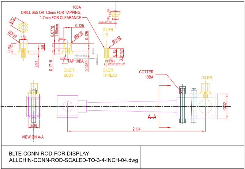
BLTE Conn Rod CAD Display Drawing
I tried to get as much detail and possible from the WJ Hughes drawing into my own drawing but bear in mind that my Conn Rod is half the size of the WJ Hughes drawing.
Machining The Components
The next section shows how the various components of the Connecting Rod were machined. note that not all operations are covered. There are over 75 photos taken during the machining process, far to many to show here. However, if I have missed a point and you have a query, please do not hesitate to send me a quey vi the Contact Form, or leave a comment below.
The Machine Tools Used
Apart from the Oiler and lid, the main parts for the BLTE Conn Rod were machined on my two big machine tools, namely the Argo mill (a Bridgeport clone):-
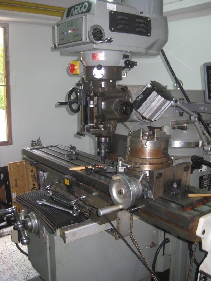
My Argo Mill (Bridgeport Clone) In Workshop
and the big KINWA CH-450 X 1100 (11″ X 28″) lathe:-
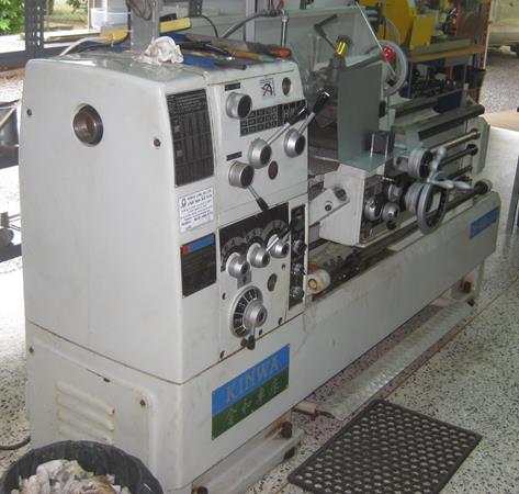
KINWA CH-450 X 1100 (11″ X 28″) Lathe
Machining such tiny parts on big machine tools does have it’s drawbacks but once the principles are understood there are advantages. The main thing to bear in mind is to keep plenty of bulk in the stock from which the part is being machined and to avoid placing cutting-tool pressure on small machined areas.
I learned a trick or two about machining small parts from Joe Pieczynski’s YouTube Channel and also there is a whole article is a whole article dedicated to making very small parts on big machine tools on the ModelEngineeringInThailand.com website under the Gauge 1 LMS 2F Tank Locomotive section.
Machining Photos 1 – Turning the Conn Rod


Hi Alan,
Sorry to hear you are not fully recovered, take it easy my friend.
Very nice work on the connecting-rod, I will have to take another trip down to see it when you finish the model.
FYI on the nuts and bolts, I found keeping a selection of Hex stock a real pain, so recently I made all my bolts from round stock.
Using the printable tools I uploaded a few months ago I printed them to scale and put the prints in my reference book, now when I want 1 or 2 unusual nuts or bolts I measure the tip to tip diameter and the flat to flat diameter of the bolt or nut from the print out and turn a blank with shaft and thread and the top being the diameter of the point to point, then the last step is set the indexing chuck to the flat to flat diameter and cut the flat sides of the hex. Is super quick easy and I can make nuts and bolts to any size thread pitch or material.
Impressive workmanship! Having recently machined a few parts myself requiring 0.5mm end mills, I appreciate the level of difficulty of machining such tiny parts.
A huge congratulations!!
Dear Alan,
I hope you are well again. As we get older, we have to accept that there will be more problems, but so be it.
As for your knowledge of the precision models you make, I take my hat off to you. They are very beautiful, but then you do have very good lathes and milling machines at your disposal.
Keep up the good work and good luck with it. It’s important to have a hobby that gives you satisfaction.
Peter, many thanks for your kind words and understanding.