Questions About Silver Soldering A Boiler
These questions arose as I was building the copper steam boiler for my 3/4″ scale Burrel model traction engine to a 1950 design by Bassett Lowke but could equally apply to any model copper boiler.
I have the boiler barrel and all the boiler plates formed (flanged) ready for silver soldering (after drilling the holes for bushes and water tubes).
But there are two questions I have before proceeding to silver soldering.
Please refer to the photos below in order to appreciate the questions.
General View Of The Boiler
Below is a general view of the boiler showing the ‘downcomer’ at the right hand side. The steel bar is just a packing piece to hold the parts of the boiler in place for the photograph.
General View Of The Boiler
Close Up Photo Of The Wet Backhead Or Downcomer
This boiler is a simple ‘pot’ boiler that will be provided with water-tubes running from the underside front of the boiler into the wet backhead or as the Bassett Lowke drawings call the downcomer. (This type of boiler is sometimes called the “smithies” type. )
The picture below is a close up photo of the downcomer.

Close Up Photo Of The Downcomer
Close-Up Of A Gap Between Boiler Plates
The next photo is a closer photo showing the juncture of the Boiler Barrel, the Throatplate and the Downcomer (Backhead). There is a small triangle where the plates don’t quite meet and this forms a triangular hole.
Close-Up Of A Gap Between Boiler Plates
Identification Of The Triangular Gap Between the Boiler Plates
The next two photos shows this triangular gap clearly identified and marked in yellow colour.
Identification Of The Triangular Gap Between the Boiler Plates
Identification Of The Triangular Gap Between the Boiler Plates (2)
Question 1 About Silver Soldering The Boiler
The Triangular Gap
1) There is a triangular shaped ‘hole’ where the flanged plates do not exactly match up. This is quite small – a 1.7mm drill will just fit in the gap. My concern is that silver solder will just run through the gap and not seal it. I could put a piece of 1.7mm diameter copper wire in the hole or try to make a better fit from a piece of copper rod by filing.
The next photo shows the size of the gap dimensionally – a 1.7mm drill will just fit in the hole.
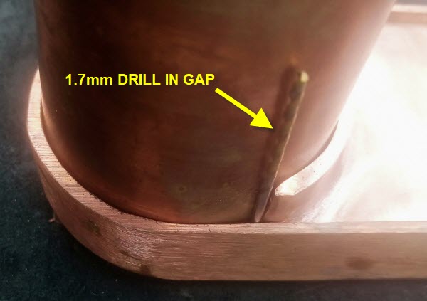
A 1.7Mm Drill Will Just Fit In The Hole
Is this really necessary or will silver solder fill the gap as it is?
Please leave your opinions/comments below.
Question 2 About Silver Soldering The Boiler
Boiler Throatplate Non Lapped Joint
2) Because of lack of space in this tiny boiler there is not enough room to flange the sides of the throat plate, so I am suggesting a non-flanged (non-lapped) joint.
The copper is thick – 7/32″ (just under 1/8″) for the size of the boiler and there is an ‘upstand’ of 1/6″ formed by the flanges of the backplate (Backhead) so that a fillet of silver solder may form.
All the dimensions of the boiler plates and the location of the proposed non-flanged joint are shown in the photo below.
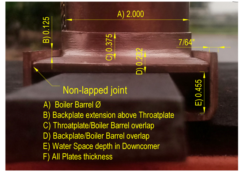
Boiler Throatplate Non Lapped Joint Location And Dimensions
Boiler Throatplate Non Lapped Joint Location And Dimensions
Is this acceptable practice? I personally doubt if the silver solder will form a fillet unless a high temperature solder is used. Any suggestions?
Les, just thinking aloud I could maybe put a strip of coper say 1/8 X 1/8″ on the inside of the Throatplate (the wet side), fix it with copper rivets (1/16″ dia) and then braze it up all before inserting Throatplate into the boiler assembly. Then put another 1/8″ strip on top per your suggestion and silver solder up with a lower temperature silver solder.. All depends upon the position of the holes for the water tubes. I need to check this out in the workshop.
But don’t forget our discussions before about Austen Walden’s Twin Sisters design that was a copper boiler with no flanges at all.
Les, my first reaction is agree with your suggestions.
I’m not sure of the boiler pressure – maybe 60 psi.
Intending to do some stress calculations using both ‘traditional formula’ and the Yield Point Method formula.
https://modelengineeringinthailand.com/forum/index.php?threads/the-yield-point-method-full-original-article.47/
Afternoon all
As far as the joints go a strip of copper riveted in place before soldering is the way I would go. And at the same time shape the top end to run up into the triangular area. this will fill the void. And be held solid while soldering. Thing alway want to move as soon as I approach with the heating touch.
Geroge, that’s a great suggestion.
I am adding separate strips of copper that will increase the surface area of the silver soldered joint and for two additional reasons:-
1) The strips of additional copper will be riveted and pre-brazed to the Backplate and thus form a ‘shelf’ upon which the Throatplate can sit whilst it is silver soldered in place.
2) These strips of copper will be extended up to the centre of the boiler and therefore close off those triangular openings I would otherwise have.
This, by the way, was George’s suggestion so thank you George, a great idea.
This conversation is continued on the Forum at:-
https://modelengineeringinthailand.com/forum/index.php?threads/bassett-lowke-traction-engine.55/post-361
The non lapped joint is in a difficult place, a lot of thermal expansion is taking place in that area, however the solution is not too hard just use a 7/32 x 7/23 bar and place it in the joint, the silver solder will form a 7/16 joint.
The largest bending moment is across the 2″ dimension so 7/16″ should be ok, shear in the .455″ direction is the main factor and that is dependent on the boiler pressure.
For sure the triangle is too big to fill with silver solder.One thought for the triangle is to use copper fillings as a filler, using fine copper fillings they will act as a filler while the silver solder will act as the binder, Pack the fillings in but not too tight as you want the silver solder to coat the fillings, the addition of copper should work as a thickener to hold the silver solder while it cools.