Mikes CNC Slant Bed Lathe Part 06 – Electronics
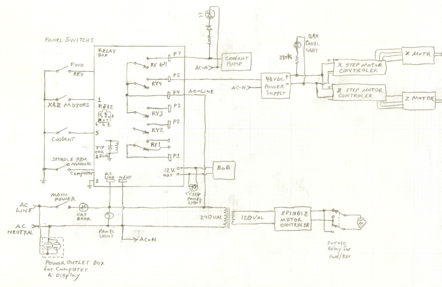
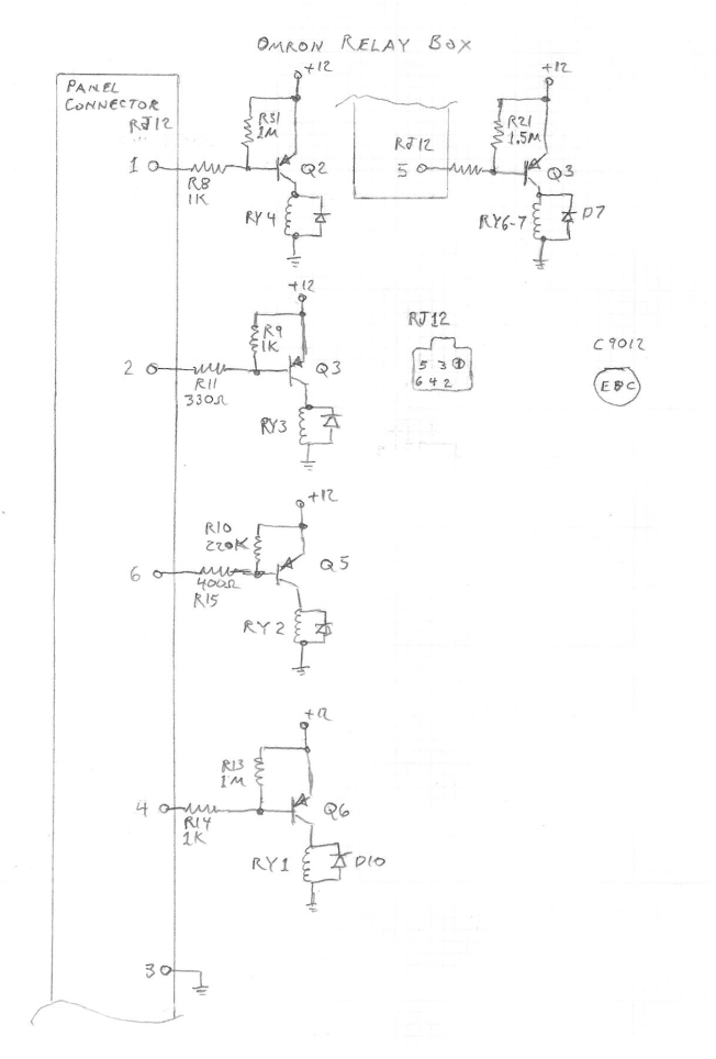
Block Wiring Schematics
| Main Control Computer: Dell Optiplex 755 SFF desktop computer (replaced laptops used earlier). |
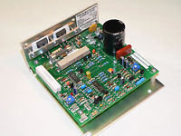
| Variable Speed Controller for DC Spindle Drive Motor ($160.55) – www.Geminicontrols.com |
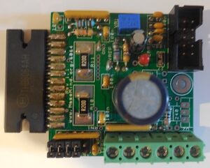
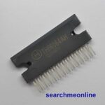
| Ordered 5 THB6064AH Stepper Motor Driver chips via eBay – $42.00 free shipping from central China. I smoked several of these by accidentally pinching & shorting the motor output wires during motor tuning setup. |
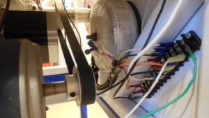
| Toroidal transformer (step down 240 vac to 120 vac) & power strip are mounted below electronics bay. |
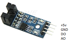
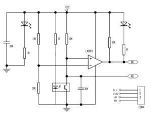
Description: Arduino Slotted Optocoupler Module |
| • Groove Width: 5mm • LED output state indicators • Obscured => output high; unobstructed => output low • Module slot unobstructed, receiver conduction: DO output low. Obstructed, DO output high • The comparator output, more than 15mA • Operating Voltage: 3.3V-5V • Single centered hole for easy installation • PCB Dimensions: 3.2 x 1.4cm / 1.25” x 0.55″ • Uses wide voltage range LM393 comparator |
Spindle Index & RPM Sensors
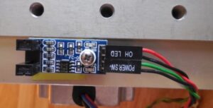
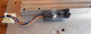
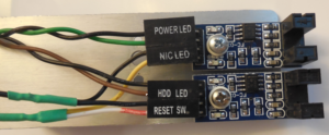
Single aluminium bracket holds two Optocouplers; Brown-Black leads show 30 slot wheel on the spindle, Green-Black leads show single Index tab (made from an old credit card, super-glued to the hub).
| Black Analog Out Green Digital Out Black Ground Yellow +5vBlk Analog Out Brown Digital Out Black Ground White +5v |
That concludes this section of the DIY CNC Slant Bed Lathe build Part 06
Future Pages
We’ve now covered 16 out of 19 topics!
Next section will be about the Coolant System
Other Pages In This Section
