Mikes CNC Slant Bed Lathe Part 02 – CAD Drawings
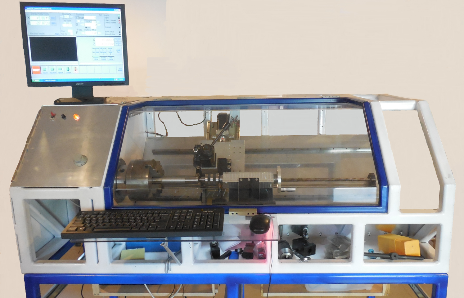
General View Of The CNC Slant Bed Lathe
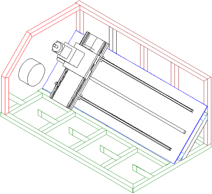
Below is a different view of the Home-Made DIY CNC Slant Bed Lathe.
CAD Drawings
Here are some initial CAD Drawings of the CNC Slant Bed Lathe prepared by Mike using TurboCAD 18.
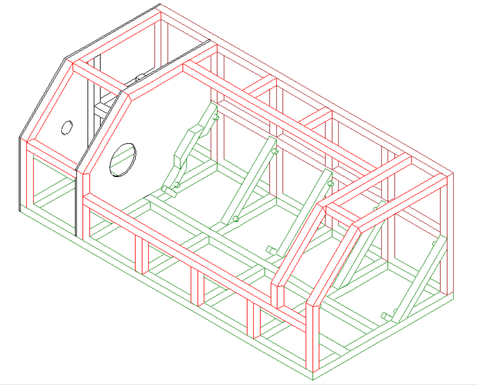
Slant Bed Lathe Main Frame Cage
The Cage is 25” Deep X 21” High X 56” Long made from 4mm thick wall Steel Tube & 2 Steel plates, 6mm for the plate nearest the chuck, 3mm for the end plate.
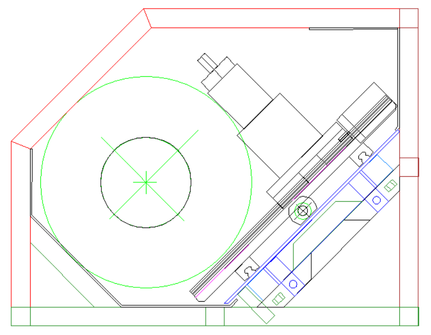
The next drawing shows the end view looking from the Tailstock end. The slant bed of the lathe can be clearly seen.
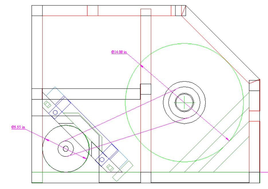
Next is the Headstock end view, shown without the carriage.
Then we come to the main slant bed itself showing the Lonitudinal Guide Rails and the Crosslide. In this CAD drawing the lathe Spindle is not shown.
Lathe Slant Bed
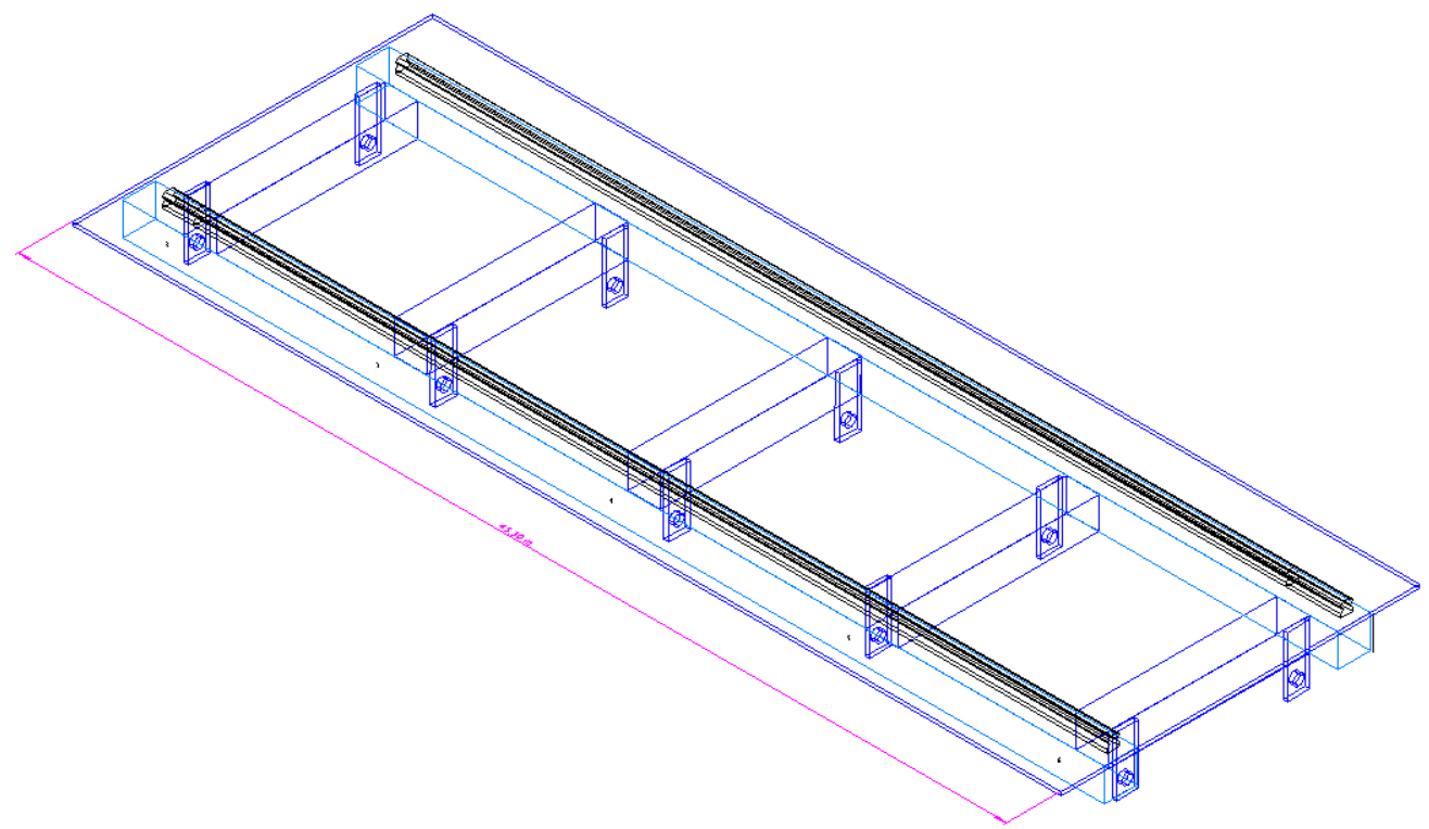
A separate weldment was made from 38mm X 38mm square steel tube and it bolts to the main lathe cage to allow for adjustment to compensate for any possible cage miss-alignment.
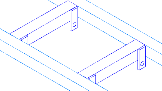
Below are the CAD drawings for the separate weldment.
The 10 Steel tabs shown above were replaced with 5 steel plates which were welded onto the 5 cross tubes and are used to bolt the bed assembly onto the cage; the pre-drilled holes (or slots) are over-sized for the bolt size used and allow for X-Y adjustment of the entire bed assembly.
Future Pages
Here we have only covered the first of 19 sections to be covered in future pages. 18 more sections to follow.
