Introduction
Trunnions to carry the expansion link were supplied as part of a laser-cut set of parts for the Gauge 1 LMS 2F Tank Locomotive.
Unfortunately, I lost one pair of the originals so had to make replacements.
How would you go about making two of these and how long should it take?
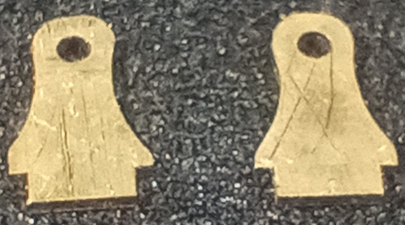
Here is an actual size of the finished trunnions compared to a standard safety match head:-
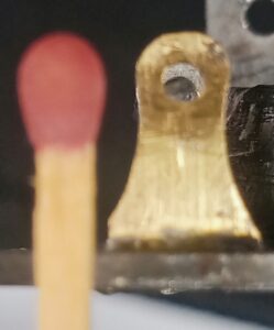
Gauge1 LMS 2F Trunnions Expansion Link Actual Size
Width is 1/4″, Height less than 7/16″, hole 1/16″ dia and thickness 1/32″.
How would you go about making these items?
Basically there are two schools of thought.
- METHOD 1 – Bench Work
- METHOD 2 – “Over The Top” Brute Force Milling and DRO
METHOD 1 – Bench Work
I guess that true craftsman (used to working in these small sizes i.e. a clock or watchmaker) would have them knocked out in an hour or so using a coping saw and Swiss files.
METHOD 2 – OTT Brute Force Milling and DRO
This is what I chose to do. Only took me two days!
I Loctited four sheets together – two brass inners for the Trunnions and two ally for the sacrificial outers.
I used to use superglue for this application but thought that high strength Loctite would grip better. Loctited and clamped for 24 hours.
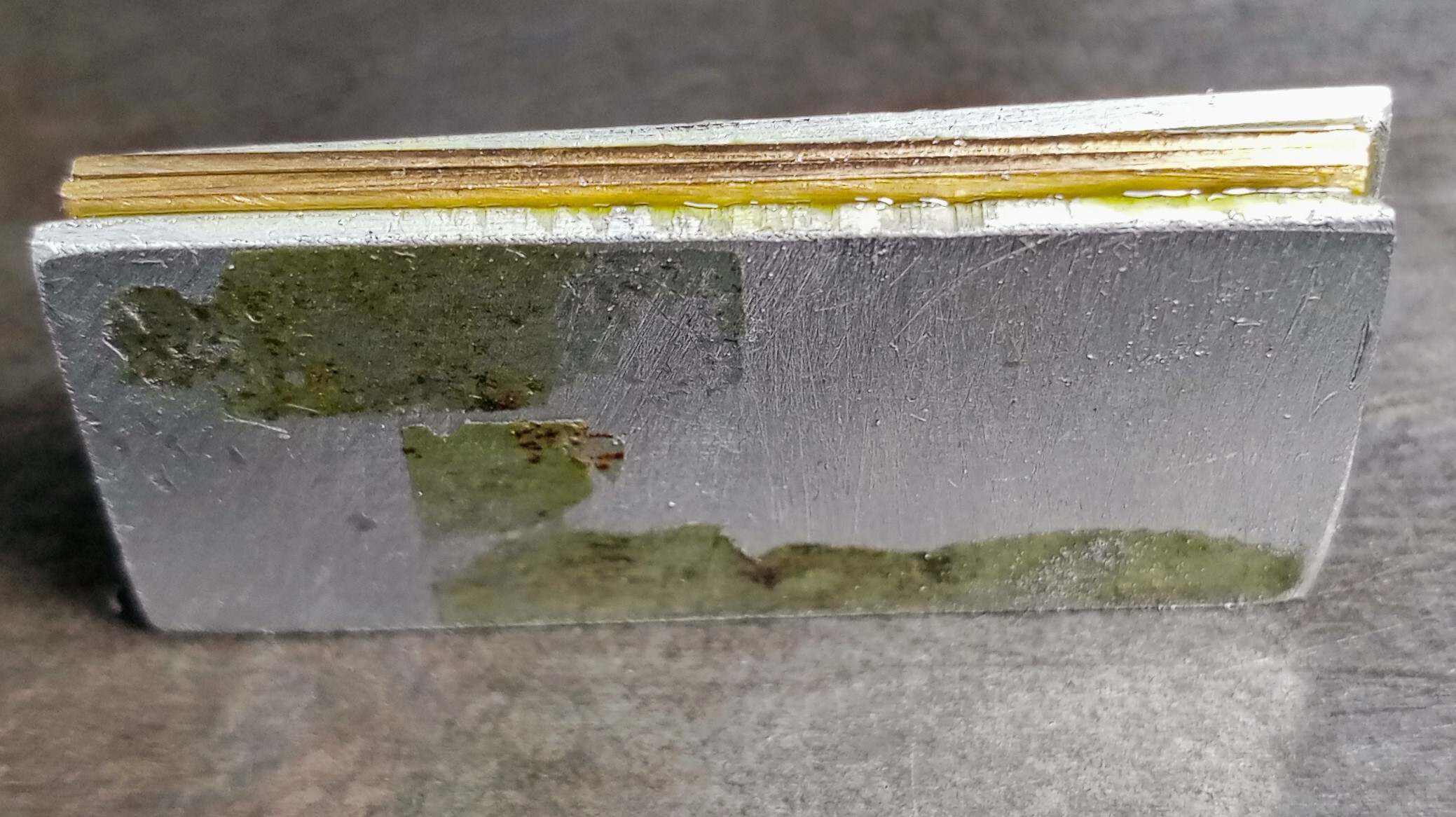
Gauge 1 LMS 2F Trunnions Expansion Links Layers
Used the cloth trick to drill round holes.
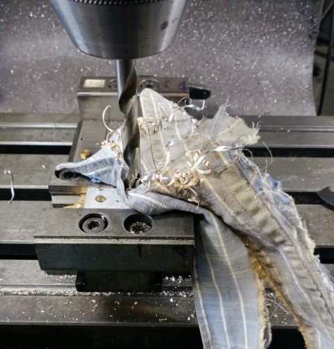
Gauge1 LMS 2F Trunnions Expansion Links Drilling
By the way, this trick actually works! Try it next time you are drilling sheet metal.
It seemed to work here too. The final drill is 5/8″ dia. Holes looked round and free from distortion.
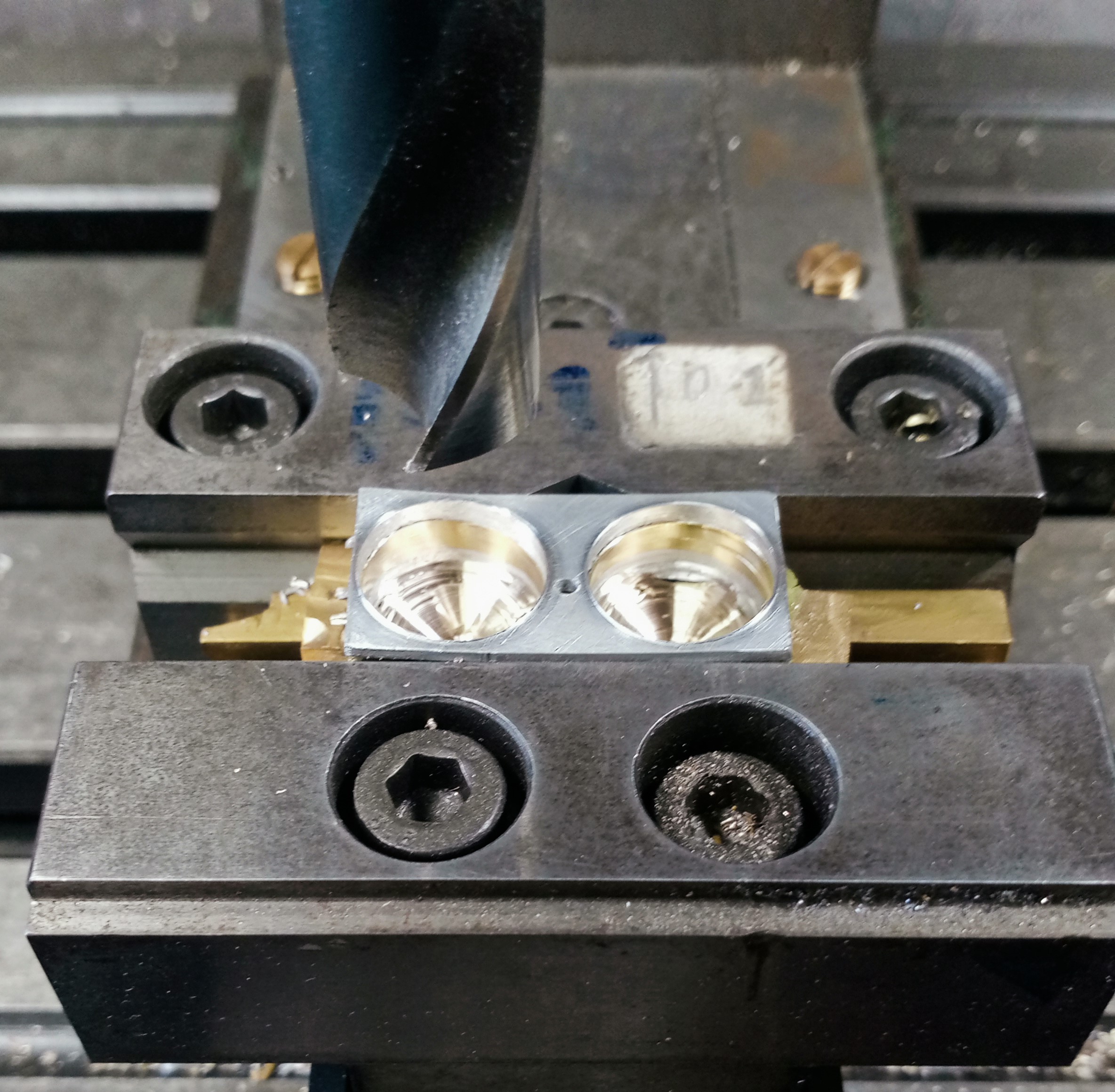
Gauge1 LMS 2F Trunnions Drilling 5/8 in diameter
But on releasing the vice jaws the whole pack of plates fell apart and were severely bent with large burrs.
I did intend to cut the final hole size by means of a 5/8 in end mill but I didn’t have one. An end mill would have been far better.

Gauge1 LMS 2F Trunnions Drilled Split 0
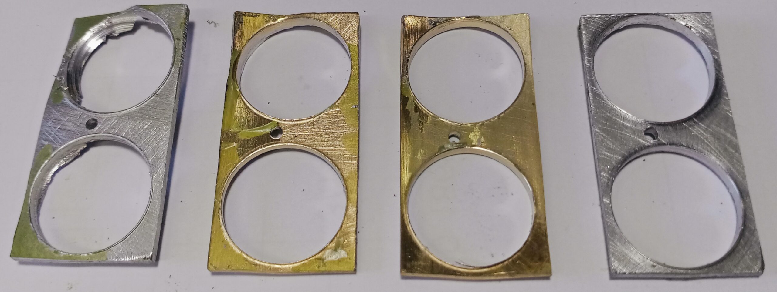
Gauge1 LMS 2F Trunnions Drilled Split 1
Obviously, the Loctite fared no better than superglue would have.
Undeterred and determined to rescue the parts I cut off the unwanted parts and things seemed better.
Gauge1 LMS 2F Trunnions Drilled Trimmed
I put a 10BA set screw through the holes to hold the two brass parts together, clamped with a 10BA nut and sweated the two parts together using soft solder paste, in recognition that neither superglue nor Loctite would hold.
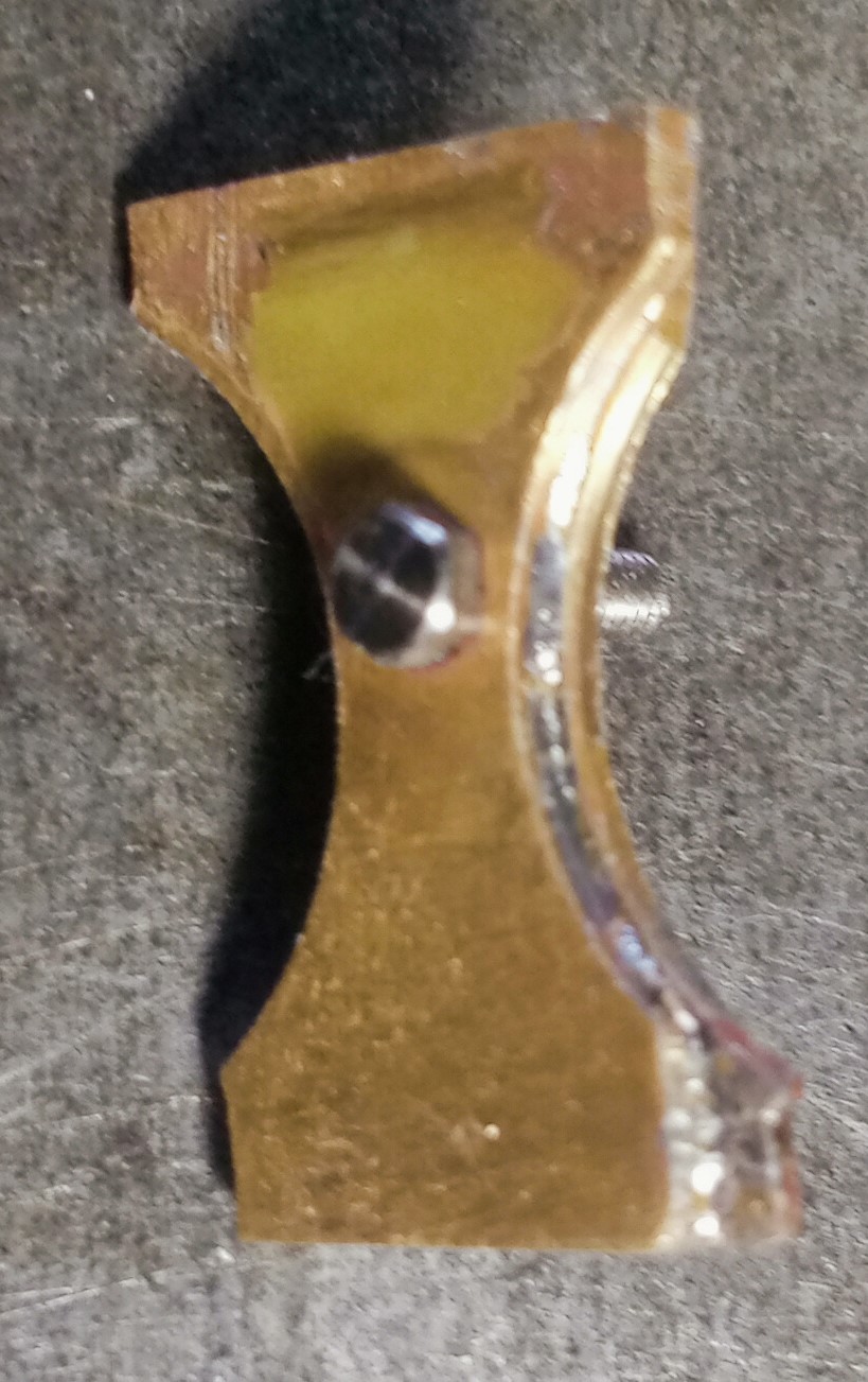
Gauge1 LMS 2F Trunnions Expansion Links Soldered Pieces
Then I cut off the extra thread with a pair of wire cutters.
I could have cried!
The cut went OK but the two brass parts shot across the workshop like bullets.
I swept up. I took all the things off the shelves. I swept behind the shelves. I lifted this and I lifted that and then at last.. what did I find? Dirt. And more dirt!
No brass parts.
I could have cried! I was resigning myself to making new parts when I saw them. The point is that the workshop brush does not sweep up such small items.
Anyway, I could now get on with the finishing.
I milled the tab insert steps on the big mill. No problems with 0.050″ cuts.
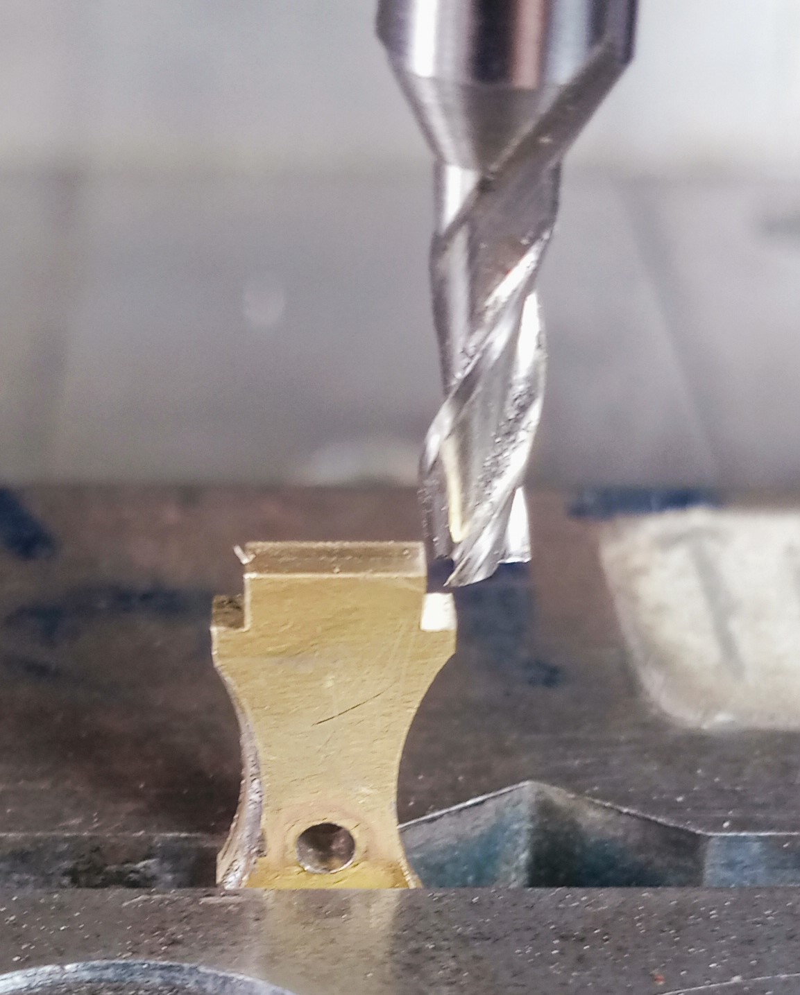
Gauge1 LMS 2F Trunnions Expansion Link Final Milling
The width at the top of the parts is just 3/16″ (5mm) wide, the two parts soldered together are 1/16″ (1.6mm) thick.
Comparing Tiny Parts With The Size Of My Milling Machine
Just by way of comparison, below is a photo of my large Argo Milling machine upon which I undertook these works.
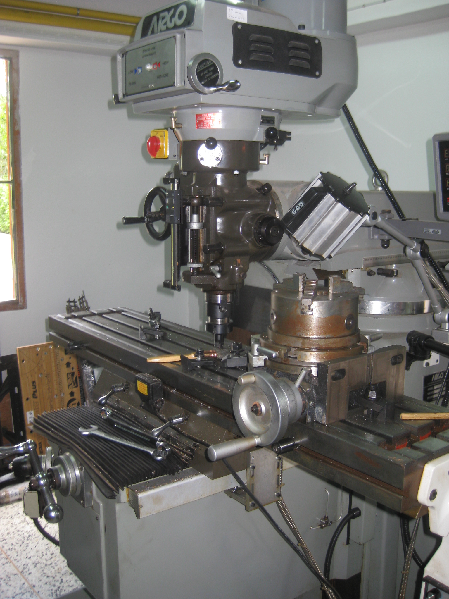
My Argo Mill (Bridgeport Clone) In Workshop
The table on the Argo (Bridgeport Clone) milling machine is 48″ (4ft or 1,200mm) long.
After Milling to Final Dimensions
In the picture above (Gauge1 LMS 2F Trunnions Expansion Link Final Milling) you can see on the left-hand side that the two radii made by the 5/8” drill do not line up exactly and had to be filed to final size.
Next I did the final stages of making the 5/64″ radius around the 1/16″ dia hole at first using filing buttons and end milling followed by filing.
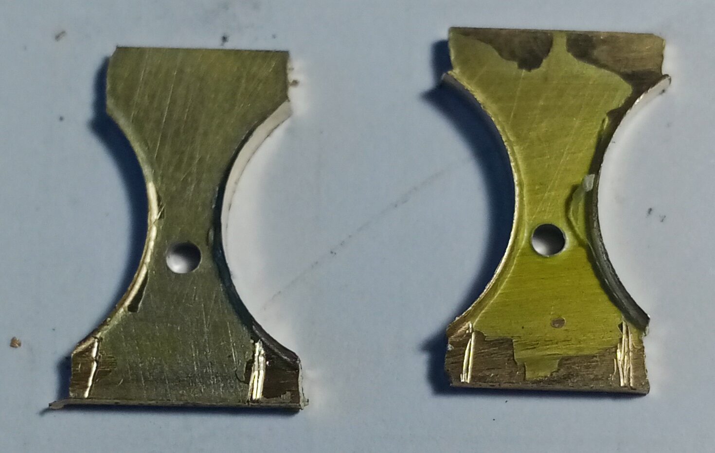
Then I separated the two parts.
Gauge 1 LMS 2F Trunnions Expansion Links
The scratches were of no consequence – the parts will be painted. But suppose this was to be the finish? Parts ruined by scratches?
Then they were soldered into position on the valve gear sub-frame.
Soldering Tip
Here is the soldering setup. I’m not using a soldering iron nor any flame. I’m soldering with a hot-air solder gun
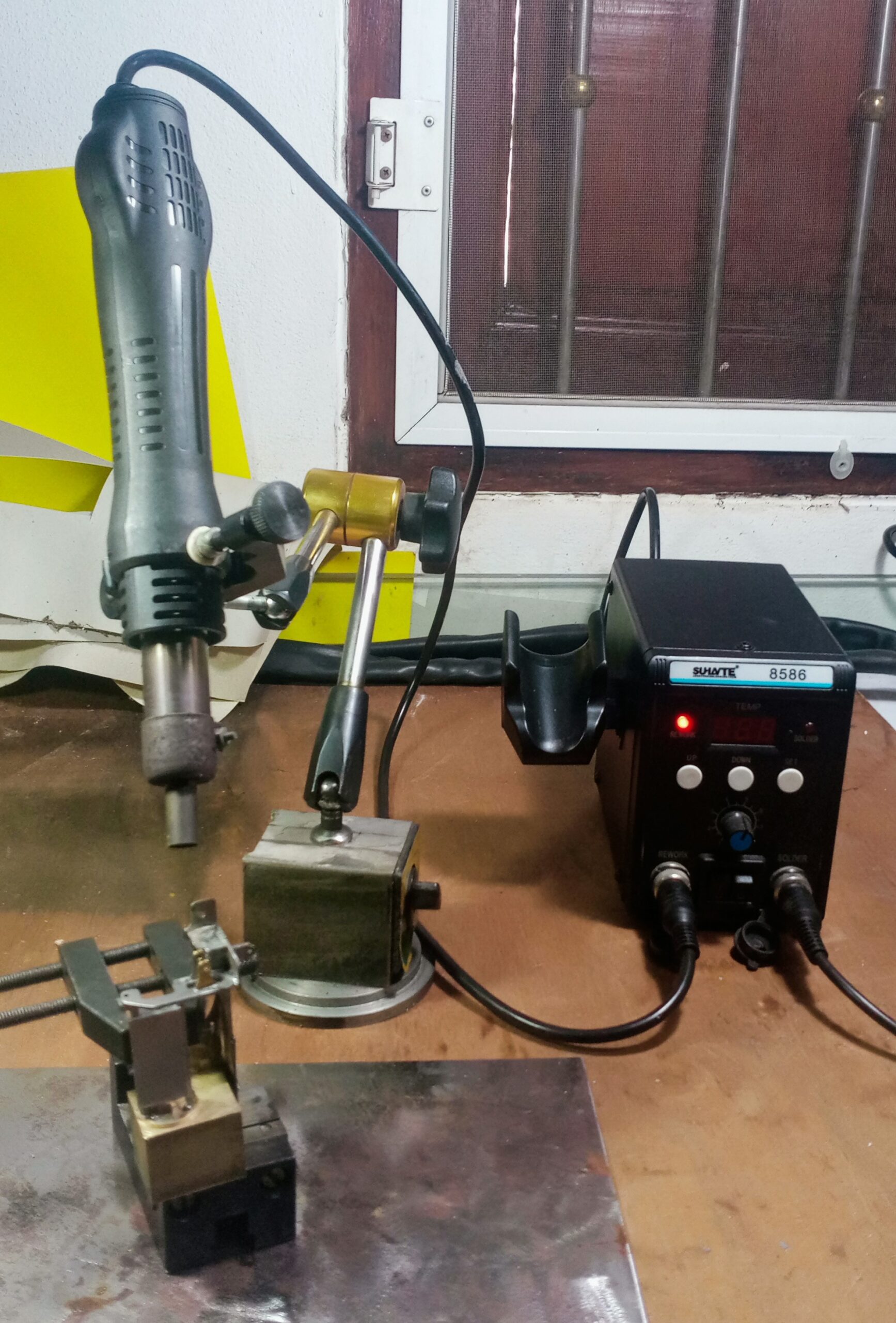
Gauge1 LMS 2F Soldering Heat Gun Station
For small parts like this and even larger like the complete valve gear sub-frame I now use this hot-air soldering gun made for use on electronic PCBs.
Plenty of temperature (up to 500 C) and good control over heat direction.
Together with soft solder paste, soldering small parts suddenly becomes a lot easier.
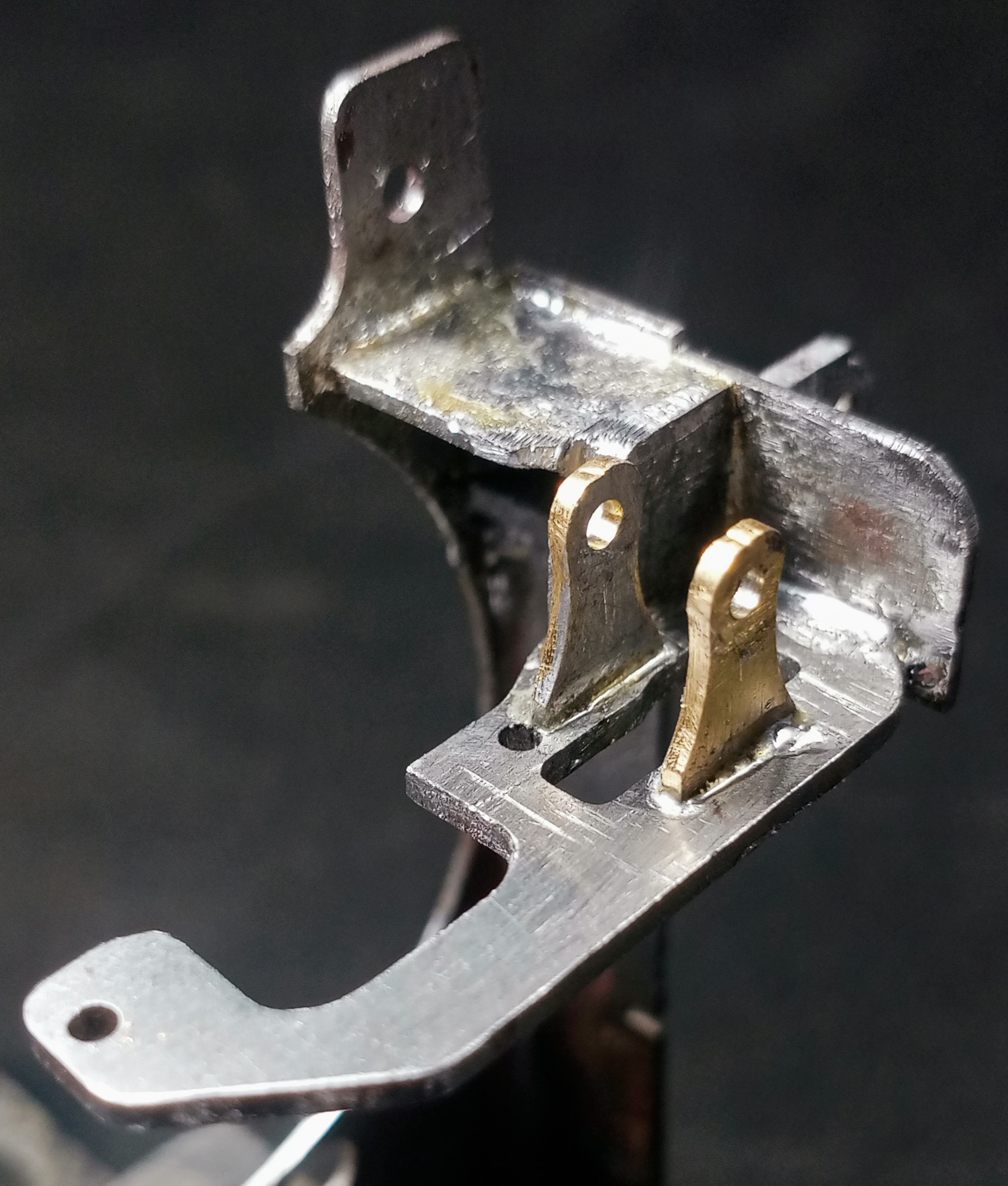
Gauge1 LMS 2F Trunnions Expansion Links Mounted
Lessons Learnt
- Loctite is no better than superglue when fixing thin plates to be machined.
- When drilling big holes in this sheet try using an endmill, not a twist drill.
- Use a hot-air soldering gun and solder paste for small parts.
- Consider using thicker plate than final thickness to allow sanding out of scratches.
- Relying on the mill DRO to accurately position holes is not reliable.
Final Conclusion
Was this machining method faster/more accurate than making purely by bench work – cutting and filing?
It depends upon your skill and available tools of course. But I bet none of my many needle files could have produced that tiny rectangular tab with the square corners made by the end mill – accurate to within a thou or so. For one thing the files always leave a radiused corner.
Join the Announcement List
Please Join the Announcement List to be notified when this website is updated.
Please Add Your Comments
And please add a comment below and let your friends know about ModelEngineeringInThailand.com
Hi Alan,
I’d use a piercing saw and a die-filer. Then draw file to get a good edge.
But if the dimensions were critical you could use a rotary table on the mill for the curves.
Many thanks Andrew, yes that’s a good suggestion – if you have a die filer. Even then the die filer must accept small enough files and making those sharp corners accurately wouldn’t be easy.
Fortunately I do have a die filer. Yes you can put in small files – a 3-square would be useful for sharp corners. Just grind a safe edges on 2 of the 3 sides so you can get into the corners.
Hi Alan,
First, your machining method is far more creative than what I would do.
The trickiest machining aspect I see is the 0.031” material thickness. I would sandwich the metal stock between two sheets of 1/8” plastic sheet. Clamp the sandwich flat on the milling table. Using a 1mm or 1.5mm diameter end mill, CNC cut the entire part, including the 1.7mm hole, milling through the top plastic sheet and 0.020” into the bottom plastic sheet. This method will leave a small radius on both corners, which can be milled away as you did on your parts, or hand filed if the dimensions are not critical. Using a small diameter end mill to cut the hole won’t tear or deform the thin metal as would a typical drill bit..
I used this procedure to machine the reed valves for my wobble-plate air compressor I made 2 years ago. The valve material is 0.010” thick stainless. The size of each reed valve is similar to your part. All the holes in the reed valve plate are milled, not drilled.
Congratulations on successfully completing the trunnions.
And very well documented. The write up was a good read. The only change I would suggest is to clamp the sandwich to the milling table. with a thick bit of perspex under it to lift it clear of the table. I say perspex become I have a lot and it makes a good spacer. But any scrap material would do. By clamping to the table you would avoid the distortion and separation of the parts.
At least you now have a well swept floor.
I too have just brought a heat gun and will give it a try for soft soldering parts. But most of the time I use silver solder.
Good luck on the next small component.