Build Your DIY Robot In You Own Home Workshop
Hello and welcome to the world of robotics.
In this first of a set of articles we will jump right in and create our own simple but fun robot.
Introducing Otto The First Robot To Build
For our first model I have chosen to use OTTO, due to the simplicity and support surrounding this simple dancing robot it gives the builder an easy start and some experience in some of the basic areas of robotic control.
These are the simple steps to follow:-
1. Download and print the parts.
(Note if you do not have a 3d printer but still want to join the fun, you can purchase the printed parts, just search for OTTO Kit)
2. Purchase and assemble the electronics (do not worry its cheap and easy)
3. Program the controller to move OTTO
Try downloading a few different programs or make your own. Take a look at this movie to get ideas:-
OK, lets go 😊
1. Download and print the parts
I recommend starting with https://www.printables.com/model/31955-otto-diy-build-your-own-robot, this is the basic building block all other otto’s are built from. Its also the same bits that are in the purchased kit.
Click on the download link on the right-hand side it will take you to a list of parts.

Printables Download Page for DIY Otto Robot
Start by downloading OttoDIY_ManualSparkfun_SHIELDnano.pdf This is a great step by step instruction guide that will help you assemble the basic Otto.
You will also see links to a set of parts, note you only need one head and one body, the list contains some variations to accommodate different single board computers and switches.
Let’s start with the Arduino Nano 3.0 and Nano Base (I’m not recommending these sellers, they are just examples, shop around 😊)
https://www.lazada.co.th/products/arduino-nano-30-nano-base-mini-usb-100-cm-i3898972487-s14973078271.html
With the basic Nano and base board, we need the basic head OttoDIYHeadV13_NanoSHIELD.stl
Next is the body, here you have a choice the only difference is the type of switch and type of battery.
I prefer to use a 16340 rechargeable battery and a square mini switch so I use OttoDIYBodyV11_Booster square switch.stl
Next is the legs OttoDIYLegV13.stl plus a right foot and a left foot.
Drop the STL files into your favorite slicer I use Prusa-Slicer and print the parts.
OK step 1 Done 😊Phew that was hard right.
Step 2 Acquire the other bits.
We need a controller + base, a battery and battery carrier, 4 servo’s, a small buzzer, an ultrasonic sensor and some wire’s. The following links are just for reference, feel free to shop around.
https://www.lazada.co.th/products/arduino-nano-30-nano-base-mini-usb-100-cm-i3898972487-s14973078271.html? (need all 3 pieces) 199THB
The servo types you need are the SG90 size: 42THB x 4
https://www.lazada.co.th/products/micro-servo-motor-sg90-180-48v-16kg-i4216635873-s16612571816.html
Ultrasonic sensor 26THB
https://www.lazada.co.th/products/hc-sr04-sensor-ultrasonic-i4722076611-s19473543279.html
5v buzzer 19THB
https://www.lazada.co.th/products/512095-12085-9042-3v-5v-12v-1295-16r-1285-i4568941914-s18632079804.html
16340 battery and holder 23THB
https://www.lazada.co.th/products/ultrafire-16340-cr123a-lc16340-lithium-1200-mah-37v-rechargeable-li-ion-blue-1200-mah-i388878422-s755290142.html
Wires 22THB
https://www.lazada.co.th/products/jump-wire-10-20-30-40-i3415243359-s12631633571.html
Switch 10THB
https://www.lazada.co.th/products/8585mm-6-12-tactile-push-button-switch-i3331112952-s19254895508.html
Step 3: Bring OTTO to life !!! (Evil laugh and white lab coat time)
Ok, so here is where some engineers get a bit anxious, programming a microcomputer, but fear not its actually easier than you might imagine.
For the builders that are familiar with Arduino’s it’s a simple matter of installing the Arduino IDE, selecting the processor Arduino Nano, connecting the USB cable between the PC and the Nano and downloading the firmware.
For the builders that have never done this let’s take it step by step.
There are 2 different ways to program OTTO, Otto Blockly and Arduino IDE.
- Blockly is really designed for young builders, very easy to use but the functionality is limited to the pre-designed blocks, on the other hand the Arduino IDE is basically just a specialized text editor and tool set that allows you to create and download firmware to lots of different processors.
- Because we want to go on to build more complex designs I will focus on the Arduino IDE, but worry not I will provide the code so all you have to do initially is cut and paste and follow the steps. You will however start to develop some understanding of programing and controlling servos and other sensors. (Remote controlled toys! Steam engines, Trains, etc.) sound interesting.
The first step is to install a development environment on a PC, I will focus on Windows based machines although MAC and Linux are supported, if you are using Linux, you are likely to have some programming knowledge already, MAC and Windows versions are very similar.
The PC can be a laptop or desktop any machine that has USB ports available and is running a recent version of Microsoft Windows (10 or later).
OK, so let’s install the Arduino IDE goto (https://www.arduino.cc/en/software) there you will find links for Windows, Mac and Linux. Assuming you selected “Windows 10 or later 64 bit” you should see a file download “arduino-ide_2.3.2_Windows_64bit.exe”, go ahead and install the IDE.
After install go ahead and run the program, when it first starts it will download a few libraries this is normal, you should see a screen something like this:
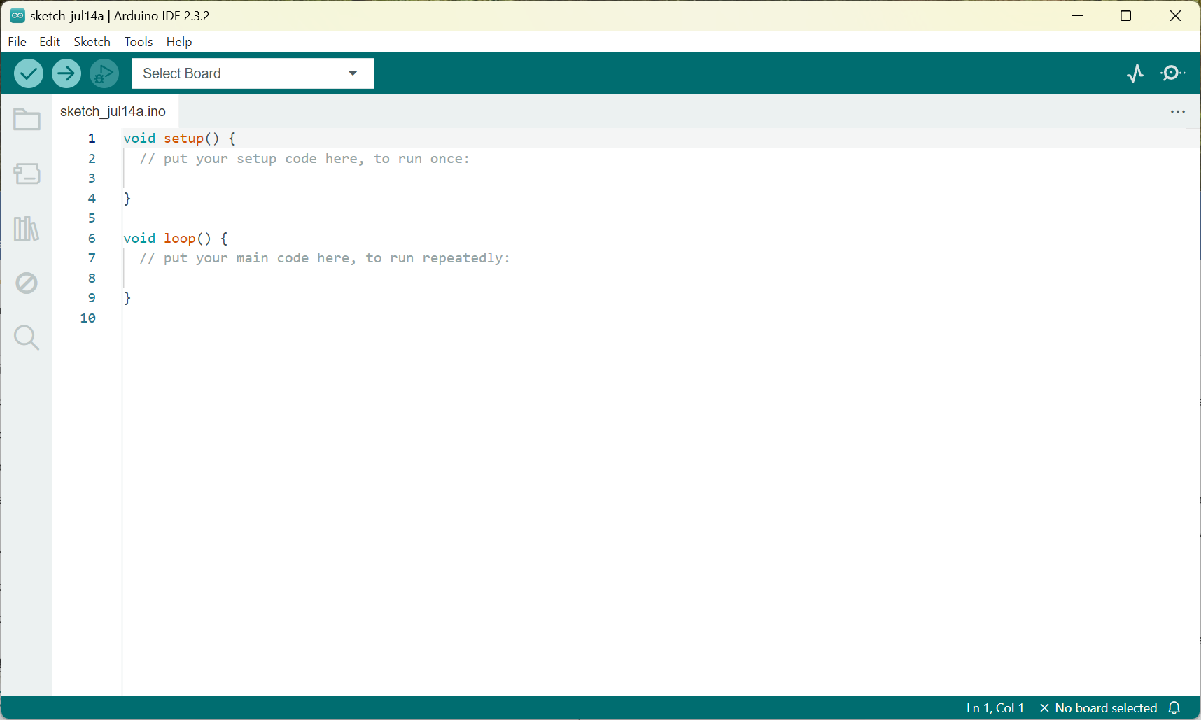
Screenshot Arduino Initial Setup for Otto Robot 01
Above, screenshot of the initial Arduino IDE Dialog Box.
The next step is to take your Nano, the base board and the USB cable and connect it all together, plug the USB cable into the PC (NOTE: make sure the base board is on an insulated surface some of the pins will power up from the USB cable).
Now back on the PC in the Arduino IDE dialog at the top select the arrow in the Select Board menu, you should see something like this: (the port number COM3 is likely to be different on your system)
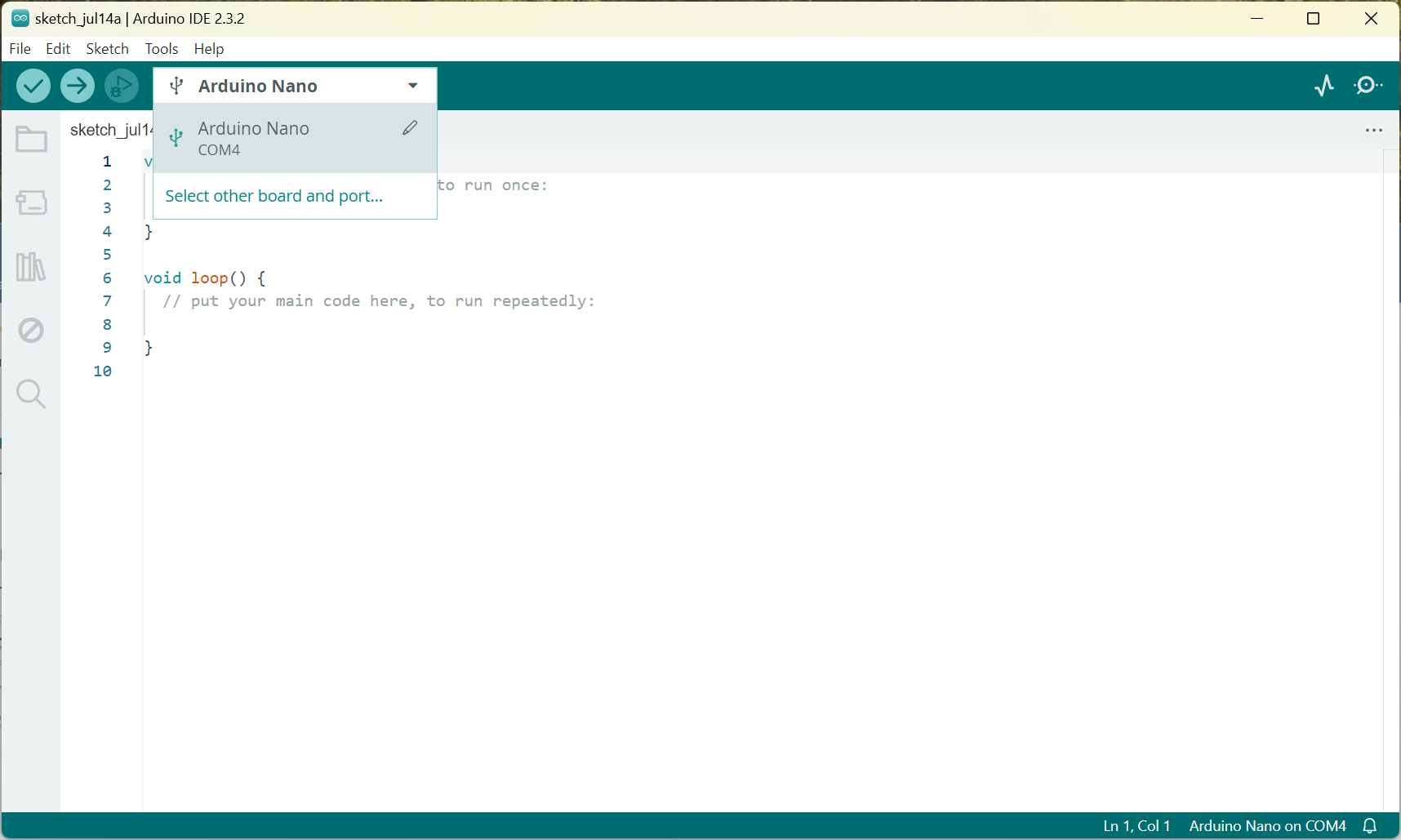
Screenshot Arduino Initial Setup for Otto Robot 02
Above, Select com port.
Click on the Unknown text, it will open a new dialog box something like the following, In the Search board field type “nano”, then click on “Arduino Nano” and select OK.
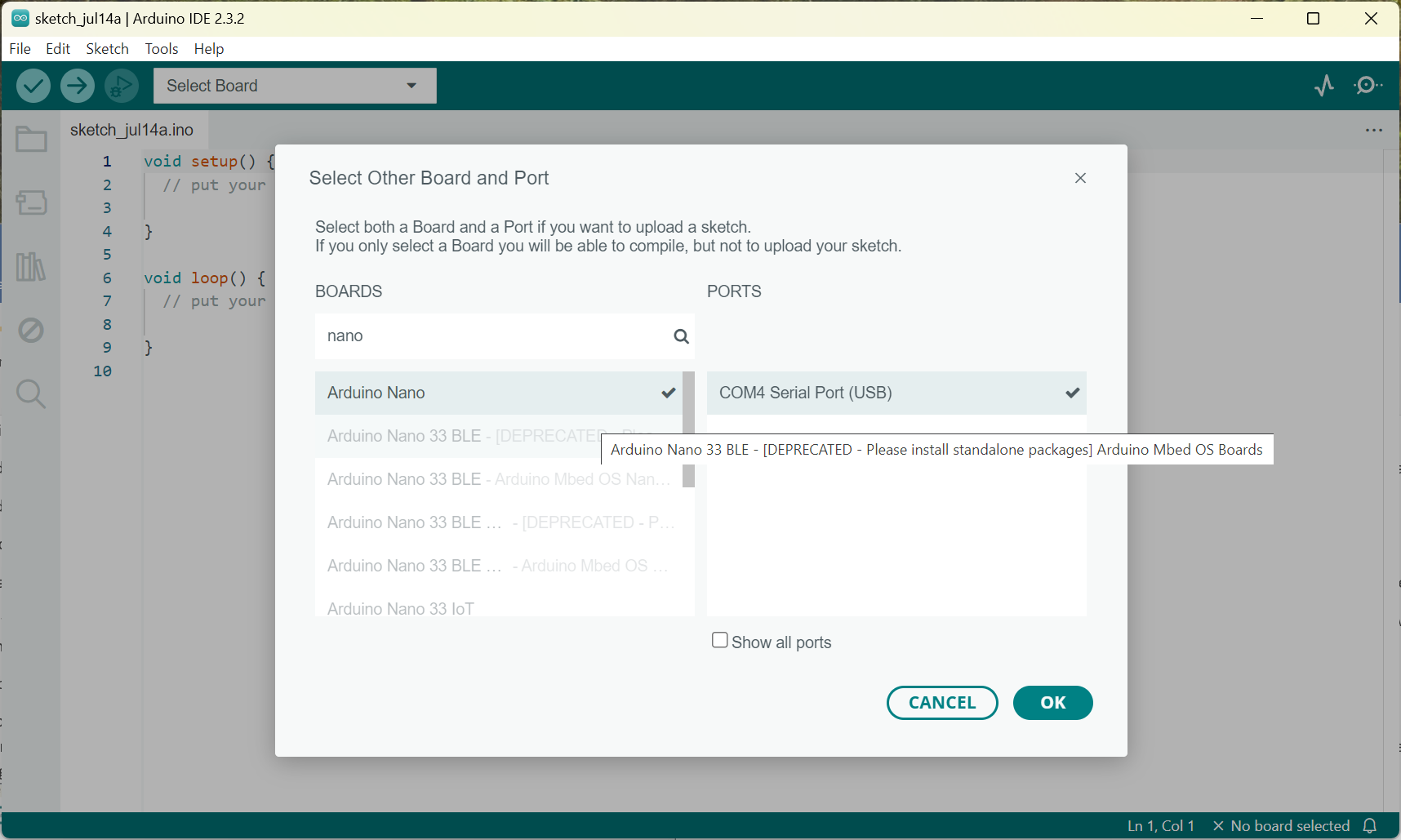
Arduino Select Board for DIY Otto Robot
Above, select the Board “Arduino Nano” and click OK.
The IDE is now configured to program the Nano, so all we need is a bit of code to tell it what to do.
Let’s install some libraries to make things a bit easier, in the IDE window at the top select Tools then Manage Libraries, scroll down until you see “OttoDiyLib” select install to install the library.
You will see in the IDE window it has created 2 functions, setup() and loop(), they will contain code to configure the Nano then continually do something until we either power off or issue a stop command.
Let’s rename our file and save it. Select File->save As and enter “Otto_allmoves” as the file name.
Now let’s take a look at setup().
Because the Arduino is very configurable, we have to tell it what connections (pin’s) to use and for what purpose, think of setup as configuration information.
For OTTO we want to drive 4 servos’, read an ultrasonic detector and turn on/off a buzzer, so we need to enter a bit of code in the setup function:
Because we are using a library, we do not have to worry about low level programing of the nano so we can simply add the library to our program by adding the following at the start of the file:
#include <Otto.h>
Otto Otto; //This is Otto!
Now we can tell nano what we connected and where they are connected
//what pins on nano are connected to parts of OTTO
#define LeftLeg 2
#define RightLeg 3
#define LeftFoot 4
#define RightFoot 5
#define Buzzer 13

//This is for the ultrasonic range finder
#define DIN A3 // Data In pin
#define CS A2 // Chip Select pin
#define CLK A1 // Clock pin
Then in the setup function we can use the library to configure the processor and set the pins to the correct state.
void setup(){
Otto.init(LeftLeg, RightLeg, LeftFoot, RightFoot, true, Buzzer); //Set the servo pins and Buzzer pin
Otto.sing(S_connection); //Otto wake up!
Otto.home(); //Move all the servo’s to the home position
delay(50);
Otto.playGesture(OttoHappy); //Otto sing a song
}
You can download the code from https://github.com/OttoDIY/OttoDIYLib/tree/main/examples/Otto_allmoves
You can see the loop function now has lots of steps, I will show you how to compress this into just a few steps in a later article. For now, you can see all the different things we are telling Otto to do. FYI the delay() function just sits and waits for the number of 1/1000 seconds to pass (e.g a value of 3000 is 3 seconds) before in executes the next command.
OK, so now we have some code its time to download it to the board.
NOTE: depending on the source of the Nano board some Chinese boards use an old serial port driver, if you see error messages and upload fails select “Tools->Processor” and select ATMega328P (Old Bootloader)
TIP: Open File->Preferences and check show verbose output during [upload]
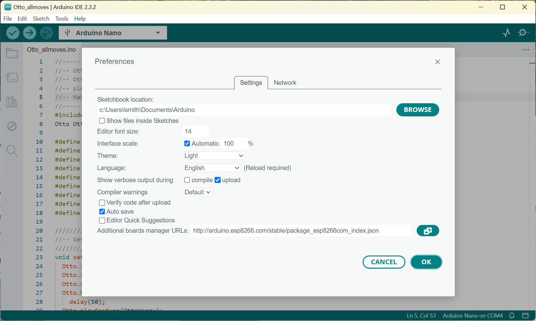
Arduino Otto Robot Show Verbose Upload Information
On the top menu select sketch->upload, you should see something like this:
It gives you some feedback on the upload so you can see what is happening.
You should see something like this:
avrdude: AVR device initialized and ready to accept instructions
Reading | ################################################## | 100% 0.00s
avrdude: Device signature = 0x1e950f (probably m328p)
avrdude: reading input file "C:\Users\lsmith\AppData\Local\Temp\arduino\sketches\961B1D1CEB6D0609ABE99A37564E6F3B/Otto_allmoves.ino.hex"
avrdude: writing flash (17392 bytes):
Writing | ################################################## | 100% 5.26s
avrdude: 17392 bytes of flash written
avrdude done. Thank you.
If you see failed to upload, its probably due to the serial interface on your board, some Chinese chips are a bit temperamental.
Try the following:
Goto tools->processor: and select [Atmega328p (Old Bootloader)]
In the bottom window at the top click on “serial monitor”
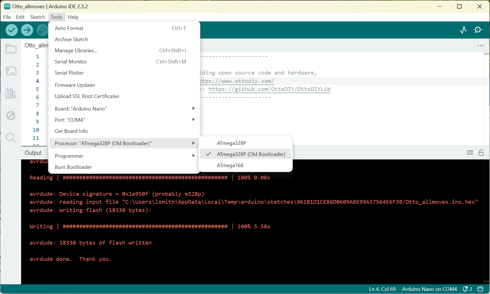
Screenshot Arduino Download Problem for Otto Robot
Above, select the Atmega328p (Old Bootloader)
Now go back to “sketch->upload”
Hopefully now you can see:
Writing | ################################################## | 100% 5.26s
avrdude: 17392 bytes of flash written
avrdude done. Thank you.
Cool you coded and programmed your controller, so let’s test it.
At this stage I like to wire everything up on the bench just to see if it all works, much easier to debug is something is not working.
So, grab the servo’s the ultrasonic detector and the buzzer and put it all together on the bench.
Refer back to OttoDIY_ManualSparkfun_SHIELDnano.pdf for wiring instructions, steps 15 to 20 but do not mount the electronics in Otto just yet.
Following the wiring diagram you should have something like this:
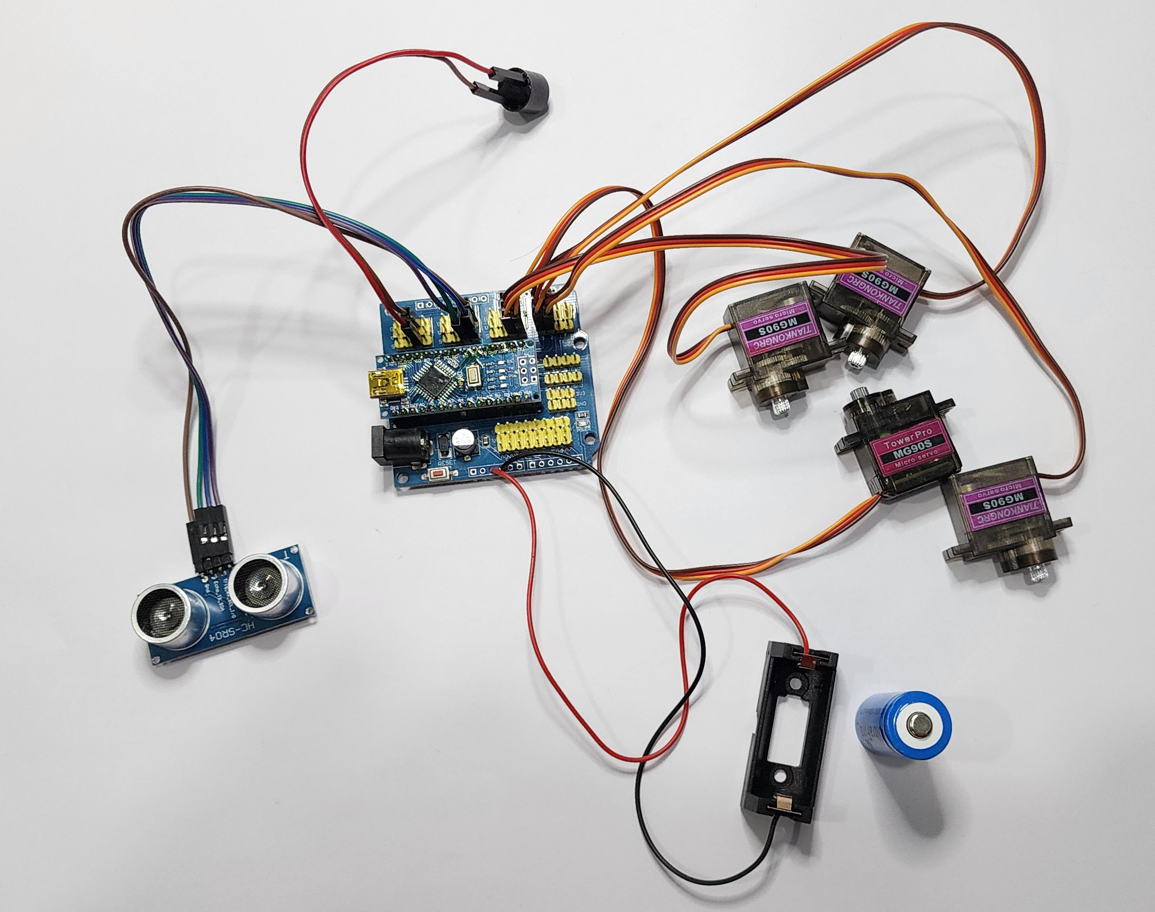
Arduino Otto Electronics Components
Above, the Otto Electronics Components
Putting the battery in it should come to life!

Its Alive – Scary Picture of Robot Builder
Well not quite its just doing what we told it to do in the loop function 😊
Now for the hard bit squishing everything into OTTO’s body and head.
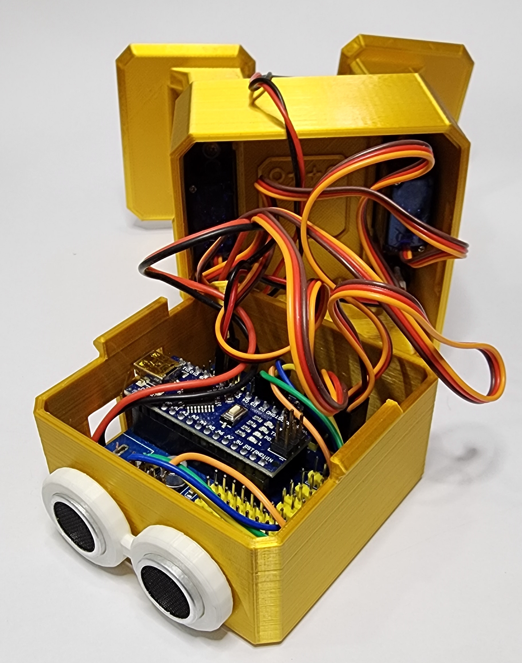
DIY Otto Robot Electronics Assembled
Above, Otto’s Brains Assembled
OK time to turn on our little guy and watch him dance and sing !
Hmmm, I think my Otto is drunk he keeps falling over? Don’t worry its normal, we can soon sober him up.
First, we need to understand a little about servos. Servos are awesome little devices, they come in many sizes and basically 3 types:
- Positional: The servo has inbuilt limit switches and stops the motor typically +/- 90 deg from center.
- Continuous: This type of servo does not have inbuilt limit switches and will continue rotating until the signal is removed, they car turn clockwise or anti-clockwise.
- Linear: This type of servo converts electricity directly into linear motion.
Servos can also range from micro to industrial with force ranging from a few grams to several thousand kilograms.
Looking at the servos in Otto we used SG90 micro servos, they are Positional and have a force of about 1.5kg/cm, quite strong for such a small device. When using a positional servo, it is important to know what position the servo is in when we attach the horn (the plastic bit that screws to the top), ideally the servo should be in the home position in the middle between the 2 limit switches.
When you assembled Otto, you might have forgotten to center the servo before installing them so the relative position of the legs and feet were unknown. Applying power to Otto caused all the servos to go to their home position, then from there we moved the legs and feet xx degrees clockwise and anti-clockwise. If the initial positioning was off, we would over rotate and cause Otto to fall over.
A second issue with Servo’s is their reaction time, given a signal the servo will move to the new position as fast as the motor can turn the gears, in an application where the load is very low, this movement is very rapid, this results in a very jerky movement and can lead to otto falling over.
So how do we fix it?
For the first issue we need to set the servo’s to the home position when we install them so we can correctly set the relative position of the limbs to match the servos, this best done by using the Arduino and a bit of code to home all the servo’s before installation, Just remove all the text from the loop function (do not delete the loop() function) down load the code and power on otto, the “Otto.home();” line in the setup() function will set all the servo’s to the home position. Later we will be adding a bit of code so we can add calibration to adjust any small errors after final assembly.
The second issue is easy to resolve with a bit of code, we will go into a lot more detail on slew rates in a later article when we talk about human movement, for now we can just break down large movements into several smaller movements with delay(xx) between each step.
So that is about it for the first article, you should take a look at https://github.com/OttoDIY/OttoDIYLib/tree/main/examples.
The Otto_allmoves code is there as well as several other examples, feel free to explore and try a few other examples, or write your own.
I hope you found this interesting, and learnt a bit about controlling Servo’s.
Next Article
Next article will be about the embedded Bluetooth and WiFi capabilities of the Arduino along with an app for your Android phone so you can control the servos from your phone.