Mike’s DIY CNC Slant Bed Lathe Part 04 – X & Y Drives
Couplers For Stepper Motor Shaft To Ballscrew
The spiral cut couplers shown on the left below were replaced with the much stronger Plum coupler shown on the right.
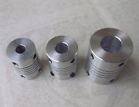 Spiral Cut Couplers |
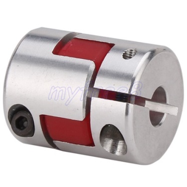 CNC Flexible Plum Shaft Coupler |
Plum Shaft Couplers Used:-
- 1pcs 8mm to 10mm Flexible Plum Shaft Coupler D25 L30
- 1pcs 10mm to 14mm CNC Flexible Plum Shaft Coupler D30 L42
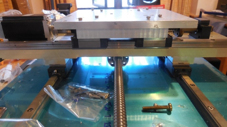
Raiser Blocks
Aluminium blocks were needed to raise the Z axis saddle and X axis Cross Slide to allow room for the anti-backlash ball nut flange. In hind sight, I should have used larger rails & linear bearings, to better match the ball screw assembly.
 Aluminum Raising Block X Axis |
 Aluminum Raising Block Y Axis |
Aluminium Mounting Bracket For Z Ball Nut
Socket Head screws fasten ball nut flange to ½” thick Aluminium mounting bracket.
 Aluminum Mounting Bracket For Z Ball Nut 01 |
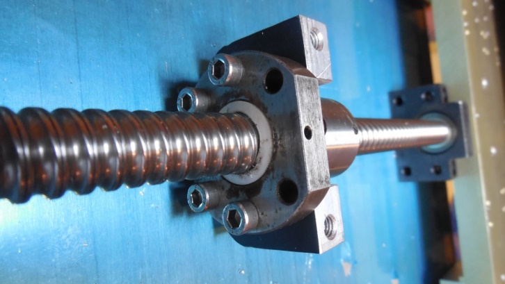 Aluminum Mounting Bracket For Z Ball Nut 02 |
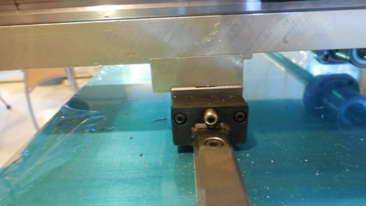
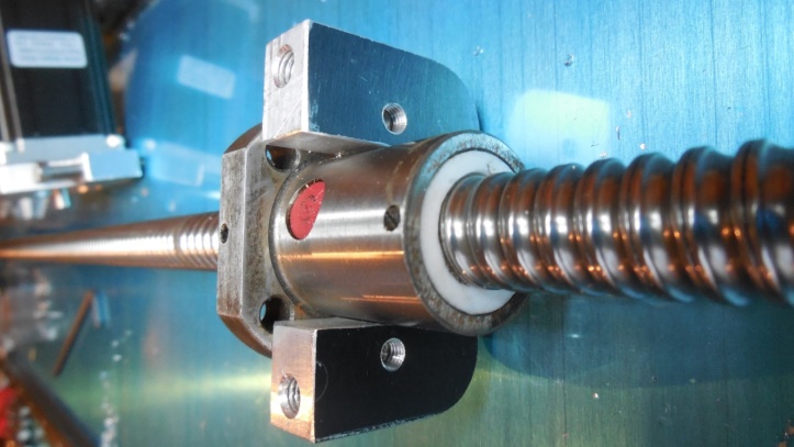
X Axis Ball Nut Mounting Bracket
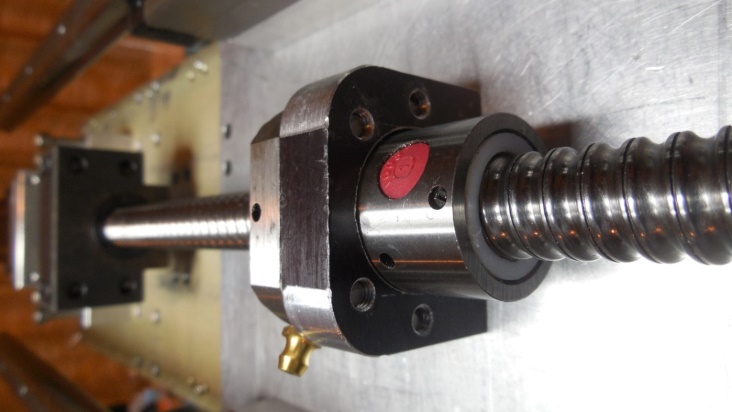 X Axis Ball Nut Mounting Bracket 01 |
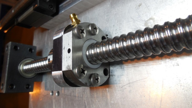 X Axis Ball Nut Mounting Bracket 02 |
Notice the ball screw bearing flange is partially recessed into the cross slide plate, providing additional directional rigidity. Pan Head screws were used because they have a lower Head space then Socket Head screws.
X Axis Stepper Motor Mounting
Nov 2015: Made mounting plate for X axis Step motor. Milled a 0.1135” deep pocket into carriage plate to allow motor shaft to align with ball screw shaft.
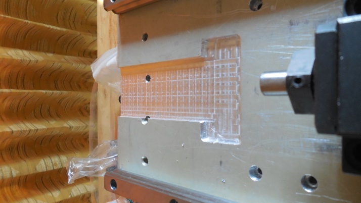 X Axis Stepper Motor Mounting 01 |
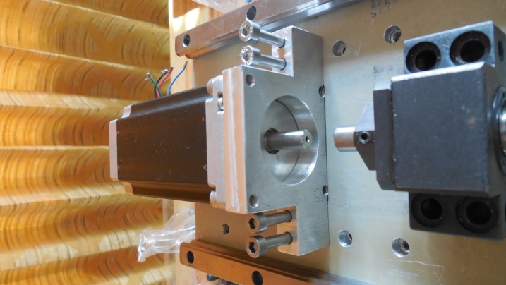 X Axis Stepper Motor Mounting 02 |
Spindle Assembly & Motor
All steel spindle parts are: SCM440
Similar to USA grade: 4140 & 4142
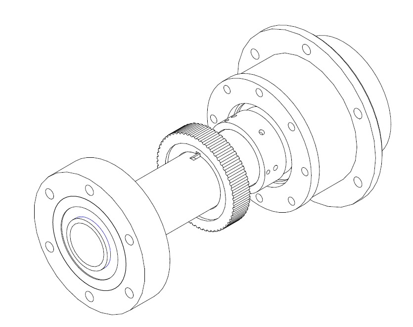
All Steel Spindle Assembly

All Steel Spindle Assembly Exploded (Seals Not Shown)
Bearings For Spindle
Purchase in USA via eBay:-
- 2 FAG 7211B-TVP-UA Angular Contact Ball Bearing, Single Row, Open, 40° Contact Angle, Polyamide/Nylon Cage, Normal Clearance, Metric, 55mm ID, 100mm OD.
- 1 Timken 210K Ball Bearing, Open, No Snap Ring, Metric, 50 mm ID, 90 mm OD, 20 mm Width, Max RPM, 5200 lbs Static Load Capacity, 9000 lbs Dynamic Load.
- SKF Seals (Qty 2) 64 x 80 x 8
Pulleys & Drive Belt
Note!! The main drive belt listed below should be replaced as it is rated at less than 1Hp at low RPM.

Pulleys & Drive Belt Specification & Cost
Belt Guides For Spindle Pulley
Belt guides for both sides of the spindle pulley. Used my home made DIY CNC mill to make the circular cuts into a ¼” aluminium plate; both guides will be screwed onto the pulley to add thickness to the pulley; will also need to make a keyway into both guides.
Using a 3/16” end mill, machined a half round slot into the motor pulley, then hand filed the round into a square for a 3/16” square key.
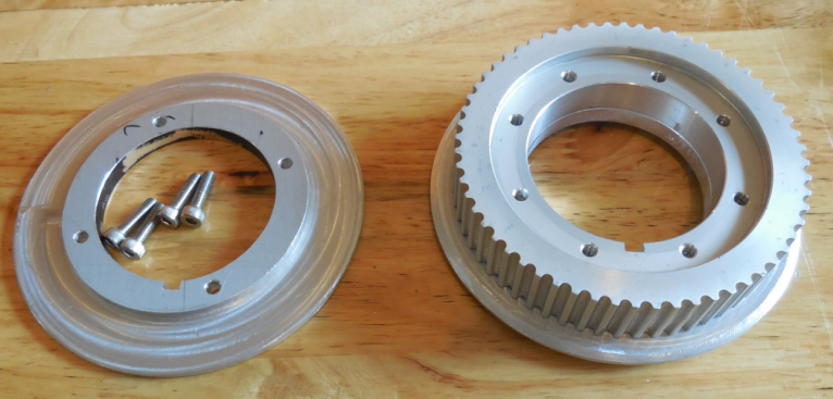
Spindle Pulley Belt Guides
Spindle Drive Motor
- 130 VDC Permanent Magnet
- 2.5 HP Leeson
- 3,600 RPM
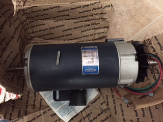 130V DC Spindle Drive Motor |
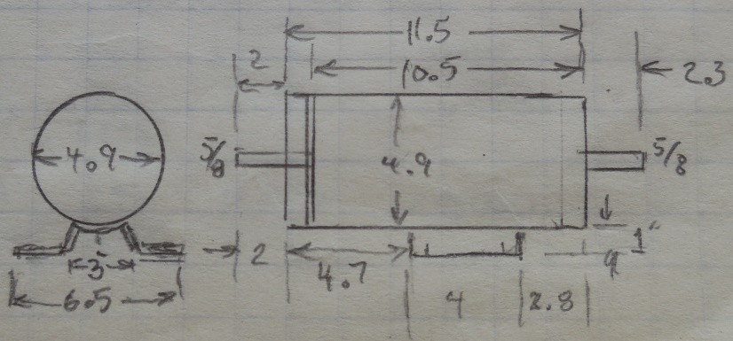 130V DC Spindle Drive Motor Dimensions |
Spindle Assembly
Spindle Assembly shown mounted into the steel frame. Timing belt and pulleys provide a 2:1 rpm reduction from the motor to the spindle.
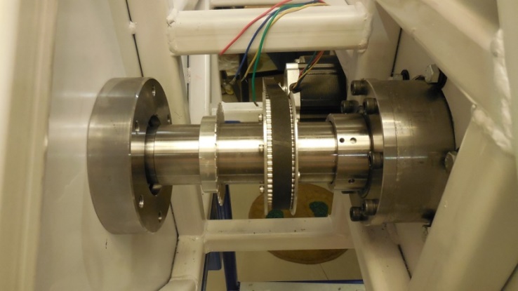 Spindle Assembly Mounted In Frame 01 |
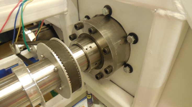 Spindle Assembly Mounted In Frame 02 |
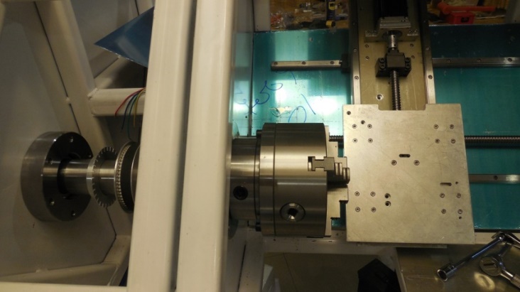 Spindle Assembly Mounted In Frame 03 |
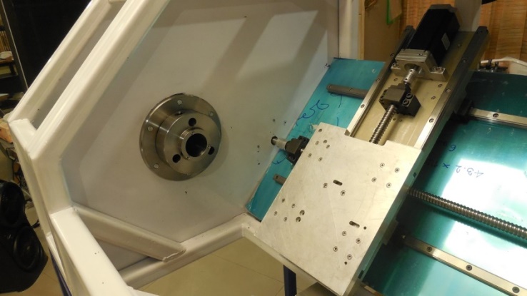 Spindle Assembly Mounted In Frame 04 |
2 shims are placed under the bottom front spindle bearing cup flange which will have the effect of angling the Z axis upwards from chuck to tail.
That concludes this section of the DIY CNC Slant Bed Lathe build Part 04
Future Pages
We’ve now covered 10 out of 16 topics!
Next section will be about the D1-4 Cams, Studs, Tailstock
Please Leave Your CommentsBelow
Please leave your comments and/or questions below. Comments will not appear until I have reviewed it. (Too many comment-spam-bots) Your email address will not be shown. Thank you. AlanOther Pages In This Section