Building The 3/4″ Scale Bassett Lowke Burrell Traction Engine Model
Having just finished the refurbishment of my 6″ scale Little Samson Traction Engine (Showmans’ Conversion) I’m straight away off building another traction engine model, a 3/4″ Scale Burrell Traction from designs published by Bassett Lowke in the 1950s.
As a young teenage boy back in the 50’s I used to read the Model Engineer magazine where the adverts for this model appeared and look at the ads with envy as we (my father and myself) had neither the money to buy the parts nor the workshop and tools needed to make the parts.
So my reason for building this model is to fulfil a young boy’s dream.
This is intended to be a full series of articles describing the construction in detail as the project progresses. I expect it to take one to two years.
3/4″ Scale Bassett Lowke Traction Engine Model Photos
01-3-4-Bassette-Lowke-Burrel-Traction-Engine
I hasten to explain that the above photos of models of the 3/4″ Scale Burrell Traction are not photos of my engine!
Front Cover Copies From Instruction Manuals
The next gallery shows some copies of the front covers of the Instruction Manuals for building the model, plus one advert as published in a magazine at the time.
01-Instructions-3-4-Bassette-Lowke-Traction-Engine
Replica Or Modernised Model Design?
At first I was tempted to make my model a close replica of the 1950’s design, as typified in the photos above. I thought that it would be a good historic record and have a good resale value.
But there are some things that I simply had to change, one of them being the spirit-fired boiler. Methylated spirits isn’t available where I live and the current standard for firing small model boilers, whether stationary, locomotives or traction engines, is by means of gas – usually incorporating a ceramic burner.
I should also go for a proper internally fired boiler instead of the externally fired ‘smithies’ type that tends to burn the boiler casing paint. But I have already purchased the materials for the ‘smithies’ type boiler as per original design and will probably stick with that.
Another feature of the original design is the fine-toothed driving gears. It would be so easy, since I will have to cut the gears myself anyway to adopt a gear tooth size more in line with scale.
The third (but not the last) thing that irritates me about the 1950’s design is the straight reversing link which look so out of place. So I will make a proper curved link as full-sized practice.
Other things I’d like to do differently if I can is to neaten the big clumsy looking steam pipework and ditto wheels.
Oh! Yet another pet ‘hate’ of the Bassett Lowke design is the ‘swervy-curvey’ shape of the hornplates. Traction engine hornplates were never like that and particularly not the Burrel engines.
I should have changed the shape at the outset, but I didn’t and since I now have the hornplates cut out to the original Bassett Lowke design I’m going to stick with them.
And don’t get me started on the boiler! (Another item)
Instructions And Drawings
I was lucky enough to find a set of the original drawings (4 Sheets at A1) and a copy of the Instructions on eBay and promptly purchased them. Here is part of one of the sheets of drawings:-
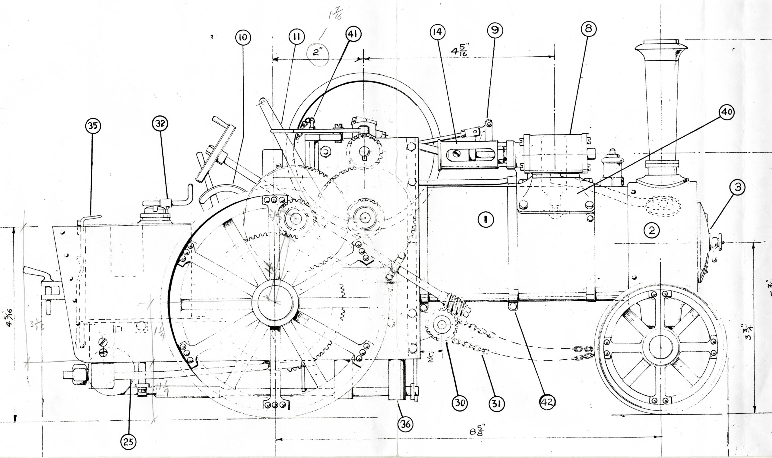
Part Of Sheet 1 Of The Original Drawings
Drawings CAD And Castings
In the 1950s, a period just after WWII had finished, model engineers workshops and workshop tools were rather rudimentary and scarce.
To help people to build this model engine Bassett Lowke made available sets of castings and finished parts as shown in the scanned image below:-
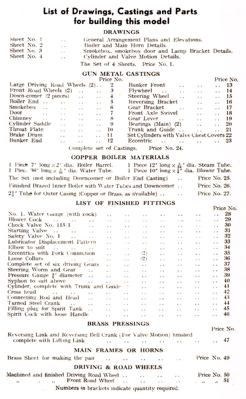
Bassett Lowke Burrell Traction Engine Parts List
In addition to offering finished machined items like the cylinder, drive gears, steering worm and wheel as well as boiler fittings, use was made of 26 castings, available from Bassett Lowke.
The drawings, therefore do not detail these parts.
So anyone building the engine today (2025+) will have to firstly make his own detailed drawings of each component and then fabricate the part or have patterns and castings made, as appropriate.
In my case, I’m making a full set of CAD drawings for all components and will be fabricating or machining them from solid stock.
I’ll be posting CAD drawings as they are finalised.
Not A simple Model
As I progress with the CAD and actually building this model, I’m beginning to realise that this ‘simple little project’ is not so simple at all. If fact, in part largely because I have to fabricate the wheels and machine from solid many other parts – casting not being available – it is a very complex project. It has almost as many parts as the 6″ scale Little Samson Traction Engine in fact! Almost every part that exists on the 6″ model is required on the 3/4″ scale Bassett Lowke Burrell model.
And, let’s not forget that almost every part that exists on the full size Little Samson Traction Engine is included in the 6″ scale Little Samson Traction Engine.
Other Pages In This Section


Les thanks for your comment. I have copied it over to the Crankshaft Spinning Freely page which is more relevant to your comments.
https://modelengineeringinthailand.com/models-alans/bassett-lowke-burrell-traction-engine/crankshaft-spinning-freely/#comment-48960
Thanks for your comment Les, I think this should have been on the https://modelengineeringinthailand.com/models-alans/bassett-lowke-burrell-traction-engine/crankshaft-spinning-freely/ page so I’ll copy it over there.
Wow looking very nice, I like the finish to the parts, I’m guessing lots of time with wd40 and fine wet&dry.
Regarding bearings and crankshaft alignment. I made all my bearings (bronze inserts) tight then used some very fine valve grinding paste I had left over from rebuilding my Bronco engine.
I used a bit of grinding paste and some wd40 then manually rotated the shafts and axles until they turned freely then cleaned everything with white spirit to make sure all the grinding paste was removed.
I was also surprised even though I took my time making sure everything was square when I first put the axles in place they did not line up perfectly.
I drilled and marked out all the plates using cnc and used the edge finder and DRO on the mill for the bearing blocks, I think the errors came from bending the plates, even though I scribed the bend lines on the cnc, bending the plates on my 5 ton press introduced +/- 0.5mm.
I did all the bending calculations so I allowed for the metal creep during bending but still the plates ended up slightly off size.